Yaskawa VS-626 MC5 User Manual
Page 180
Advanced Operation
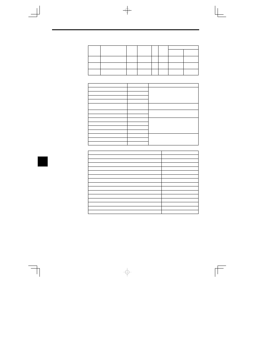
7.3.5 External Terminal Functions: H
- 42
Constant Settings
User
Change
during
Setting
Factory
Valid Access Levels
User
Constant
Number
Name
during
Opera-
tion
Setting
Range
Unit
Factory
Setting
Open Loop
Vector
Flux Vector
H2-01
Multi-function input
(terminal 9-10)
0 to 41
--
0
B
B
H2-02
Multi-function input
(terminal 25)
0 to 41
--
1
B
B
H2-03
Multi-function input
(terminal 26)
0 to 41
--
2
B
B
D
The following table shows the settings and section references for functions that are described in more
detail in this chapter.
Function
Setting
Section
Frequency Agree 1
2
Desired Frequency Agree 1
3
Frequency Detection Settings: L4-01 to L4-05 in
Frequency Detection 1
4
Frequency Detection Settings: L4-01 to L4-05 in
7.3.6
Frequency Detection 2
5
Overtorque Detection 1 (NO)
B
Overtorque Detection Settings: L6-01 to L6-06 in
7.3.6
Loss of Frequency Reference
C
Timer Functions: b4 01 b4 02 in 7 3 1
Timer Function Output
12
Timer Functions: b4-01, b4-02 in 7.3.1
Frequency Agree 2
13
Desired Frequency Agree 2
14
Frequency Detection Settings: L4-01 to L4-05 in
Frequency Detection 3
15
Frequency Detection Settings: L4-01 to L4-05 in
7.3.6
Frequency Detection 4
16
Overtorque Detection 1 (NC)
17
O
D
i
S
i
L6 01
L6 06 i
Overtorque Detection 2 (NO)
18
Overtorque Detection Settings: L6-01 to L6-06 in
7.3.6
Overtorque Detection 2 (NC)
19
7.3.6
D
Refer to Table 7.7 Multi-function Output Functions for information on the following functions.
Function
Setting
Inverter Operation Ready
6
DC Bus Undervoltage
7
During Baseblock
8
Frequency Reference Selection
9
Run Command Selection
A
Braking Resistor Fault
D
Fault
E
Minor Fault
10
Fault Reset Command Active
11
During Reverse Run
1A
During Baseblock 2
1B
Regenerating
1D
Restart Enabled
1E
During Torque Limit (Current Limit)
30
During Speed Limit
31
7