Yaskawa VS-626 MC5 User Manual
Page 75
Setting User Constants
4.2.4 Operation Mode
- 12
The “Valid access levels” column in the table indicates whether an item can be monitored in a particular
access level and control method. The codes in this column have the following meanings.
Q
Items that can be monitored in the
Quick-start
access level only.
B
Items that can be monitored in the Quick-start and Basic access levels.
A
Items that can be monitored in all access levels. (Quick-start, Basic, and Advanced)
Items that cannot be monitored in the control mode shown.
The output signal levels for multi-function analog outputs shown in the table are for a gain of 100.0 and
a bias of 0.00.
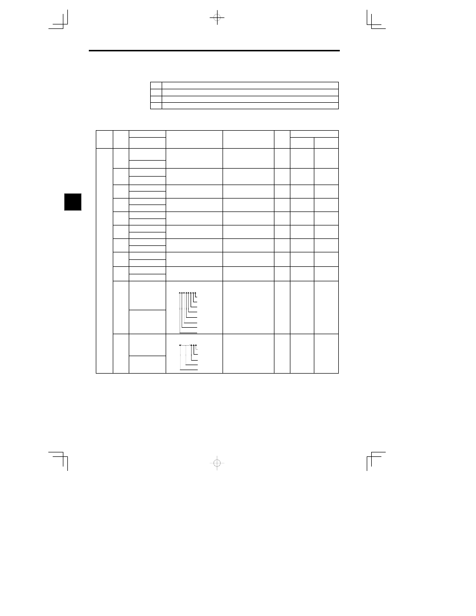
Table
4.3
Constants Monitored in Operation Mode
Func-
Con-
Name
Output Signal Levels for
Min
Valid Access Levels
Func-
tion
Con
stant
No.
Digital Operator
Display
Function
Output Signal Levels for
Multi-function Analog Out-
puts
Min.
Unit
Open Loop
Vector
Flux
Vector
U1-01
Frequency refer-
ence
Monitors/sets the frequency ref-
erence value.
Th displ
nits c n b s t
ith
10 V: Max. frequency
(0 to
r10 V possible)
0.01
Hz
Q
Q
U1 01
Frequency Ref
The display units can be set with
user constant o1-03.
(0 to
r10 V possible)
Hz
Q
Q
U1-02
Output frequency
Monitors the output frequency.
The display units can be set with
10 V: Max. frequency
0.01
Q
Q
U1-02
Output Freq
The display units can be set with
user constant o1-03.
10 V: Max. frequency
(0 to
r10 V possible)
0.01
Hz
Q
Q
U1-03
Output current
Monitors the output current
10 V: Rated current
0 1 A
Q
Q
U1-03
Output Current
Monitors the output current.
10 V: Rated current
(0 to +10 V output)
0.1 A
Q
Q
U1-04
Control method
Shows which control mode is
Can’t be output
Q
Q
U1-04
Control Method
Shows which control mode is
set.
Can’t be output.
Q
Q
U1-05
Motor speed
Monitors the motor speed
10 V: Max. frequency
0.01
Q
Q
U1-05
Motor Speed
Monitors the motor speed.
10 V: Max. frequency
(0 to
r10 V possible)
0.01
Hz
Q
Q
U1-06
Output voltage
Monitors the Inverter’s internal
10 V: 200 (400) VAC
0 1 V
Q
Q
U1-06
Output Voltage
Monitors the Inverter s internal
output voltage reference value.
10 V: 200 (400) VAC
(0 to +10 V output)
0.1 V
Q
Q
U1-07
DC bus voltage
Monitors the DC voltage of the
10 V: 400 (800) VDC
1 V
Q
Q
U1-07
DC Bus Voltage
Monitors the DC voltage of the
Inverter’s internal main circuit.
10 V: 400 (800) VDC
(0 to +10 V output)
1 V
Q
Q
Status
M
i
U1-08
Output power
Monitors the output power.
(This is an internally detected
10 V: Max. motor capacity
0 1 kW
Q
Q
Status
Moni-
tor
U1-08
Output kWatts
(This is an internally detected
value.)
10 V: Max. motor capacity
(0 to
r10 V possible)
0.1 kW
Q
Q
tor
U1-09
Torque reference
Monitors the internal torque ref-
erence value when vector con
10 V: Rated torque
0 1 %
Q
Q
U1-09
Torque Reference
erence value when vector con-
trol is used.
10 V: Rated torque
(0 to
r10 V possible)
0.1 %
Q
Q
U1-10
Input terminal sta-
tus
Shows input ON/OFF status.
U1-10 = 0 0 0 0 0 0 0 0
1: Terminal 1 ON
1: Terminal 2 ON
1: Terminal 3 ON
Can’t be output.
Q
Q
U1 10
Input Term Sts
1: Terminal 4 ON
1: Terminal 5 ON
1: Terminal 6 ON
1: Terminal 7 ON
1: Terminal 8 ON
Can t be output.
Q
Q
U1-11
Output terminal
status
Shows output ON/OFF status.
U1-11 = 0 0 0 0 0 0 0 0
1: Terminals 9--10 ON
1: Terminal 25 ON
Can’t be output.
Q
Q
U1 11
Output Term Sts
1: Terminal 25 ON
1: Terminal 26 ON
Not used. (always 0)
1: Terminals 18/19--20
ON
Can t be output.
Q
Q
4