Yaskawa VS-626 MC5 User Manual
Page 162
Advanced Operation
7.3.3 Reference Constants: d
- 24
J
Carrier Frequency: C6-01
D
The carrier frequency characteristics differ according to the control method.
x
Open-loop vector control and flux vector control: Constant frequency (The carrier frequency up-
per limit only is set.)
D
The carrier frequency does not normally need to be adjusted, but make adjustments in the following
cases:
x
If the wiring distance between the Inverter and the motor is long, lower the carrier frequency.
Wiring Distance
50 m max.
100 m max.
Over 100 m
Carrier Frequency
15 kHz max.
10 kHz
5 kHz max.
x
If there are great irregularities in speed or torque, lower the carrier frequency.
User
Change
during
Setting
Factory
Valid Access Levels
User
Constant
Number
Name
during
Opera-
tion
Setting
Range
Unit
Factory
Setting
Open Loop
Vector
Flux Vector
C6-01
Carrier frequency upper
limit
2.0 to 15.0
kHz
15.0
*
B
B
*
The setting range and the factory setting vary according to the Inverter capacity. The table
shows a value of 200 V class, 0.4 kW. (See page NO TAG.)
D
In the vector control modes, the carrier frequency is determined by the carrier frequency upper limit
(constant C6-01).
7.3.3 Reference Constants: d
J
Frequency Reference Function: d2-01, d2-02
D
The frequency reference function sets the output frequency upper and lower limits.
D
When the frequency reference is zero and a run command is input, the motor operates at the frequency
reference lower limit (d2-02). The motor will not operate, however, if the lower limit is set lower than
the minimum output frequency (E1-09).
User
Change
during
Setting
Factory
Valid Access Levels
User
Constant
Numberc
Name
during
Opera-
tion
Setting
Range
Unit
Factory
Setting
Open Loop
Vector
Flux Vector
d2-01
Frequency reference up-
per limit
0.0 to 110.0
%
100.0
B
B
d2-02
Frequency reference
lower limit
0.0 to 109.0
%
0.0
B
B
D
The frequency reference upper and lower limits are set as a percentage of the maximum output fre-
quency (E1-04), in increments of 1%.
D
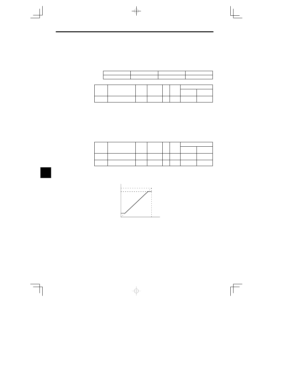
The upper and lower limits of the frequency reference are shown in Figure 7.13.
Set frequency reference
Internal frequency reference
Frequency reference
upper limit (d2-01)
Frequency reference
lower limit (d2-02)
Fig
7.13
Upper and Lower Limits of the Frequency Reference
7