Command details, Parameter details, Examples – Applied Motion RS-232 User Manual
Page 140
140
920-0002 Rev. I
2/2013
Host Command Reference
NOTE: Setting the MO command to 1, 2, or 4 - 8 overrides previous assignments of this output’s function.
Similarly, if you use the AO or BO command to set the function of the output after setting the MO command to 1 or
2, usage of the output will be reassigned and AO will be automatically set to 3.
Command Details:
Structure
MO{Parameter #1}{Parameter #2 (Flex I/O only)}
Type
BUFFERED
Usage
READ/WRITE
Non-Volatile
YES
Register Access
None
Parameter Details:
Parameter #1
Output Usage (see above)
- units
integer code
- range
1, 2 or 3
Parameter #2 (Flex I/O only)
I/O Point (if applicable, see note below)
- units
integer code
- range
1 - 4
NOTES:
• The SD command must be executed to set an I/O point as an output before that output can be designated as the
Motion Output.
• Parameter #2 only applies to drives equipped with Flex I/O. This includes the STM24-S and -Q. Parameter #2
is not defined for drives equipped with standard I/O.
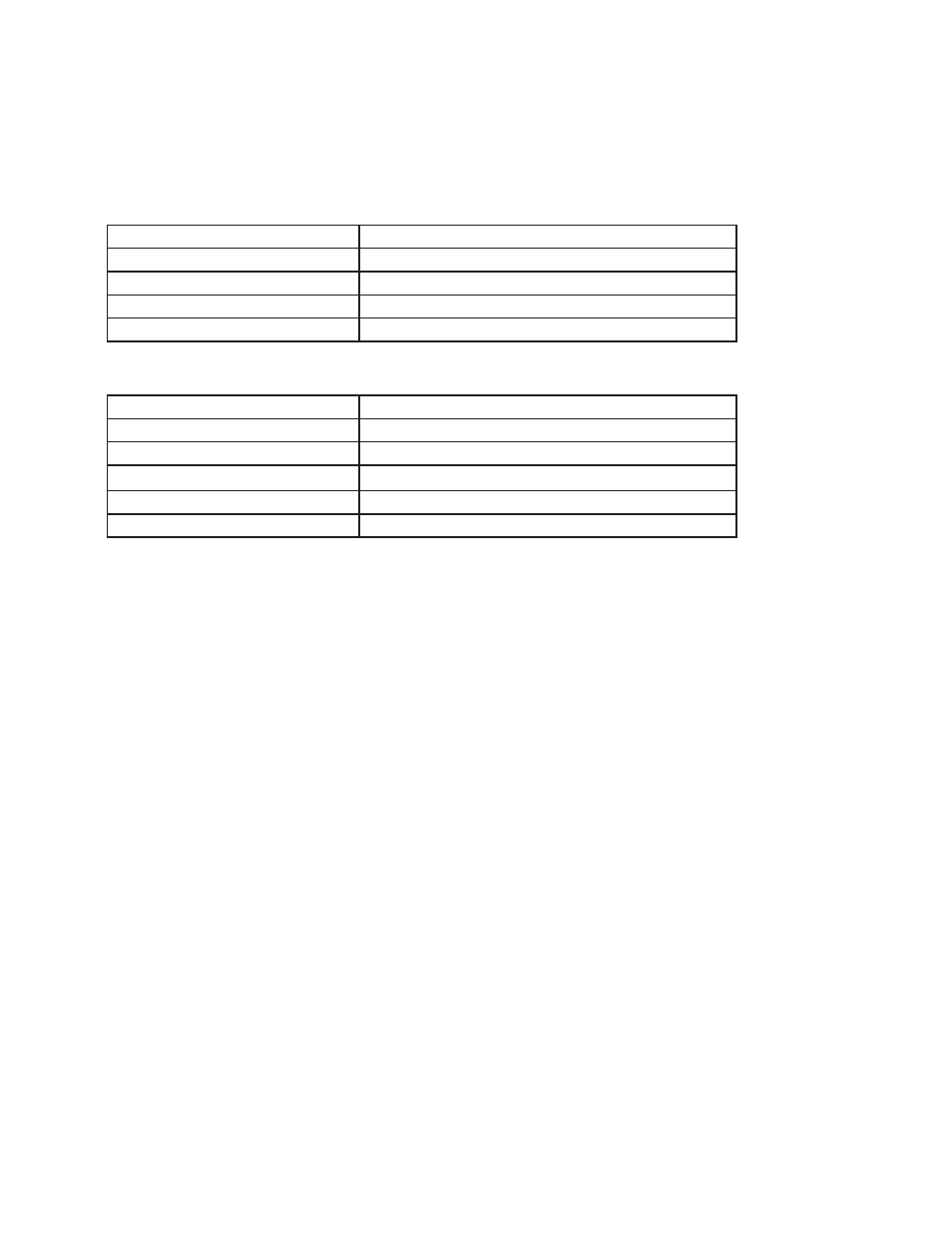
Examples:
All drives with standard I/O:
Command
Drive sends
Notes
MO1
-
Motion Output will close when the motor is not moing
MO MO=1
Drives with Flex I/O only:
Command
Drive sends
Notes
SD4O
-
Configures I/O 4 as output (see SD command for details)
MO14
-
Motion Output is mapped to output #4, and will close when the motor is
not moving
MO MO=14
STM24-S, -Q only
Command
Drive sends
Notes
MO14
-
I/O point 4 will be closed when motor is not moving
MO MO=14
NOTE: When working with digital inputs and outputs it is important to remember the designations low and high.
If current is flowing into or out of an input or output, i.e. the circuit is energized, the logic state for that input/
output is defined as low or closed. If no current is flowing, i.e. the circuit is de-energized, or the input/output is
not connected, the logic state is high or open. A low state is represented by the “L” character in parameters of
commands that affect inputs/outputs. For example, WI3L means “wait for input 3 low”, and SO1L means “set
output 1 low”. A high state is represented by the “H” character.