Command details, Parameter details, Examples – Applied Motion RS-232 User Manual
Page 26
26
920-0002 Rev. I
2/2013
Host Command Reference
(active, low), unless the SI command has been used to configure hardware enable functionality.
AI3n: The designated input ‘n’ is not used for Alarm Reset and may be used as a general purpose input.
NOTE: A rule of thumb when using the Alarm Reset function is to toggle the designated input twice whenever an
alarm occurs. That is, if the input is normally open (inactive, high), it should be closed and then opened again. If
the input is normally closed (active, low), it should be opened and then closed again.
Command Details:
Structure
AI{Parameter #1}{Parameter #2 (Flex I/O only)}
Type
BUFFERED
Usage
READ/WRITE
Non-Volatile
YES
Register Access
None
Parameter Details:
Parameter #1
Input Usage
- units
integer code
- range
1, 2, or 3
Parameter #2 (Flex I/O only)
I/O Point (if applicable, see note below)
- units
Integer Code
- range
2 or 4 (See STM24 Hardware Manual for details)
NOTES:
• For drives equipped with Flex I/O, the SD command must be executed to set an I/O point as an input before it
can be used as the Alarm Reset Input.
• Parameter #2 only applies to drives equipped with Flex I/O. Parameter #2 is not defined for drives equipped
with standard I/O.
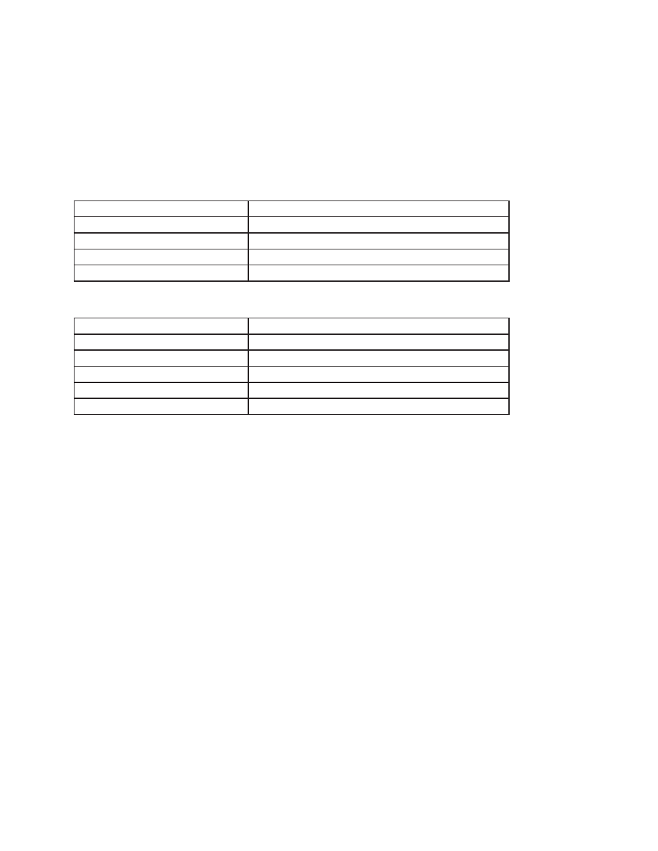
Examples:
All drives with standard I/O:
Command
Drive sends
Notes
AI1
-
Enables input to reset alarm when closed (active, low)
AI AI=1
Drives with Flex I/O:
Command
Drive sends
Notes
SD4I
-
Configures I/O 4 as input (see SD command for details)
AI14
-
Assigns input 4 to reset the alarm when closed (active, low)
AI AI=14
NOTE: When working with digital inputs and outputs it is important to remember the designations low and high.
If current is flowing into or out of an input or output, i.e. the circuit is energized, the logic state for that input/
output is defined as low or closed. If no current is flowing, i.e. the circuit is de-energized, or the input/output is
not connected, the logic state is high or open. A low state is represented by the “L” character in parameters of
commands that affect inputs/outputs. For example, WI3L means “wait for input 3 low”, and SO1L means “set
output 1 low”. A high state is represented by the “H” character.