Applied Motion RS-232 User Manual
Page 231
231
920-0002 Rev. I
2/2013
Host Command Reference
Example:
Command
Drive Sends
Notes
RLh
RLh=149
Bits 7 (UNEQUAL TO), 4 (GREATER THAN), 2
(POSITIVE) and 0 (TRUE) are set. Within a Q program
the programmer will often have more than one condition to
choose from when using the QJ command. The condition
FALSE in Q Programmer is represented by bit 0 = 0
(opposite of TRUE).
i
Driver Board Inputs (ISX)
057
Short
decimal equivalent of binary
bit pattern (see below)
All drives
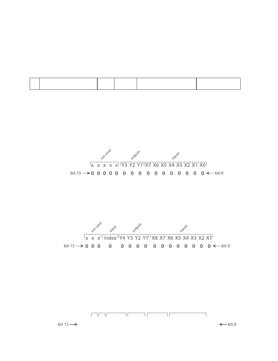
Details when executing the “RLi” command:
BLu, STAC6
The bit pattern of the “i” register breaks down as follows: bit 0 is the state of the encoder’s index (Z) channel,
also known as input X0; bits 1 - 7 represent the states of driver board inputs X1 - X7, respectively; bits 8 - 10
represent the states of driver board outputs Y1 - Y3, respectively; and, bits 11 - 15 are not used. For bits
0 - 7 (inputs X0 - X7), a state of “1” means the optically isolated input is open, and a state of “0” means the
input is closed. It is the exact opposite for bits 8 - 10 (outputs Y1 - Y3), for which a state of “1” means the
optically isolated output is closed, and a state of “0” means the output is open.
SV, ST-Q/Si
The bit pattern of the “i” register breaks down as follows: bits 0 - 7 represent inputs X1 - X8, respectively;
bits 8 - 11 represent outputs Y1 - Y4, respectively; and, bit 12 is the encoder index channel (if present). For
bits 0 - 7 and 12 (inputs X1 - X8 and the Index), a state of “1” means the optically isolated input is open, and
a state of “0” means the input is closed. It is the exact opposite for bits 8 - 11 (outputs Y1 - Y4), for which a
state of “1” means the optically isolated output is closed, and a state of “0” means the output is open.
ST-S, STM
The bit pattern of the “i” register breaks down as follows: bit 0 represents the encoder index channel (if
present), bit 1 represents the STEP input, bit 2 the DIR input, and bit 3 the EN input. Bit 8 represents
the drive’s single output, OUT. For bits 0 - 3 (Index, STEP, DIR, and EN inputs), a state of “1” means the
optically isolated input is open, and a state of “0” means the input is closed.
0
0
0
0
0
0
0
0
0
0
0
0
0
0
0
0
inde
x
X1
X2
X3
X4
X
X
X
X
X
X
Y1
Y2
X
X
X
X
not used
not used
not used
outputs
inputs