Fe - follow encoder, Command details, Parameter details – Applied Motion RS-232 User Manual
Page 78: Examples
78
920-0002 Rev. I
2/2013
Host Command Reference
FE - Follow Encoder
Compatibility: All drives
See also:
EG, MT, ST commands
Puts drive in encoder following mode until the given digital or analog input condition is met. The master encoder
channels A and B must be wired to the STEP/X1 and DIR/X2 inputs of the drive. Use the EG command before
the FE command to set the following resolution, or use the “R” register to dynamically adjust the following
resolution while following (Note that in stepper drives the “R” register is equal to 1/2 the EG command). The Step
Smoothing Filter is active in FE mode; see the SF command for details.
When the FE command is initiated, the acceleration rate AC is used to ramp the motor up to the following speed.
(Doing this prevents extreme accelerations when the master encoder signal is already at its target velocity). The
motor continues to follow the master encoder pulses until the input condition is met, at which time the motor
decelerates at rate DE to a stop using the DI command as the overall decel distance. If DI is long the motor may
not begin decel immediately after the input condition is met. If DI is short the motor may have to decelerate at a
rate faster than DE.
Before the input condition is met the motor will follow the master encoder pulses in both CW and CCW directions,
regardless of the sign of the DI command. However, once the input condition is met the motor will only stop
properly if moving in the direction set by the DI command.
When done executing the drive returns to the mode it was in before executing the FE command.
NOTE: You must use the appropriate configuration software - Quick Tuner for servos, Configurator for steppers
- to set up the STEP/X1 and DIR/X2 inputs for encoder following. Do this by choosing A/B Quadrature in the
Position mode settings.
NOTE: Take care when changing the “R” register while following because some move parameters will be scaled
as well and therefore the move may change unexpectedly.
Command Details:
Structure
FE(Parameter #1)
Type
BUFFERED
Usage
WRITE ONLY
Non-Volatile
NO
Register Access
None
Parameter Details:
(See Appendix F: Working With Inputs and Outputs)
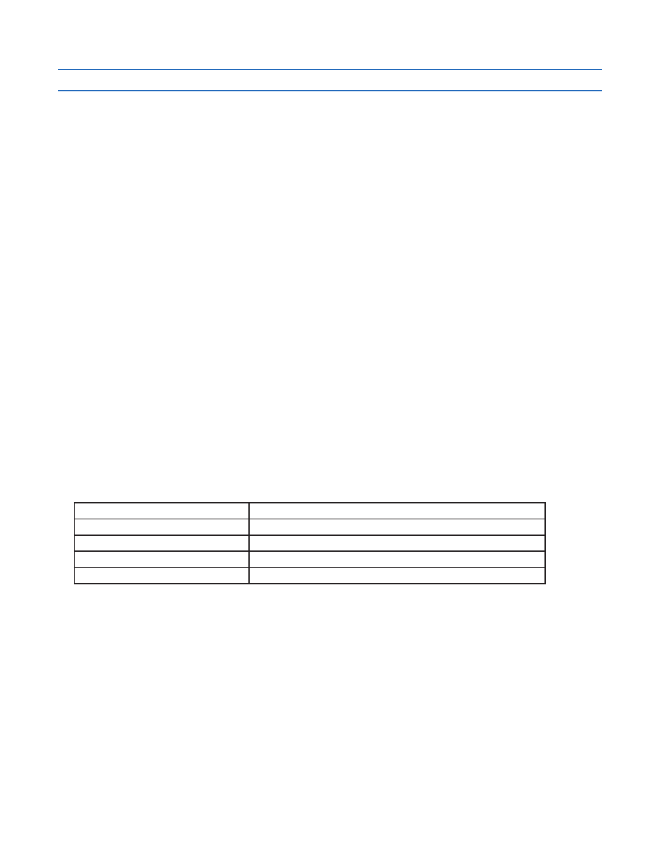
Examples:
Command
Drive sends
Notes
AC500
-
Limit acceleration in encoder following to 500 rps/s
DI8000
-
Set the stopping offset distance to 8000 counts
FE4L
-
Run in encoder following mode until input 4 is low