Applied Motion RS-232 User Manual
Page 232
232
920-0002 Rev. I
2/2013
Host Command Reference
SVAC3, STAC5
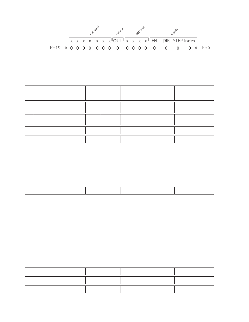
The bit pattern of the “i” register breaks down as follows: bits 0-3 represent inputs X1-X4, respectively;
bits 8 and 9 represent outputs Y1 and Y2, and bit 14 represents the encoder index channel (if present).
represents the STEP input, bit 2 the DIR input, and bit 3 the EN input. Bit 8 represents the drive’s single
output, OUT. For bits 0-3 and 14 (X1-X4 and the Index), a state of “1” means the optically isolated input is
open, and a state of “0” means the input is closed.
j
Analog Input 1 (IA1)
058
Short
raw ADC counts, 0 - 32760
16383 = 0 volts for BLu, SV,
STAC6, ST-Q/Si drives
All drives
k
Analog Input 2 (IA2)
059
Short
raw ADC counts, 0 - 32760
16383 = 0 volts
BLu, SV, STAC6,
ST-Q/Si only
l
Immediate Absolute Position
060
Long
Encoder counts (servo), or
motor steps (stepper).
All drives
m
Command Mode (CM)
061
Short
Mode #
All drives
n
Velocity Move State
062
Short
State # (see below)
All drives
Response details to the “RLn” command:
Description
Decimal Value Comment
WAITING
0
In velocity mode waiting for a command
RUNNING
1
Doing a velocity move (jogging)
FAST STOPPING
2
Stopping a velocity move (ST or SK with no parameter)
STOPPING
3
Stopping a velocity move (SJ, STD, or SKD)
ENDING
4
Clean up at end of move (1 PWM cycle, 62 usec)
o
Point-to-Point Move State
063
Short
State # (see below)
All drives
NOTE: The Point-to-Point Move State is only defined during FL, FP, and FS commands.
Details when using “RLo” command:
Description
Decimal Value Comment
WAITING
0
In position mode waiting for command
WAITING ON BRAKE
1
Waiting for brake to release
CALCULATING
2
Doing the calculations for the move
ACCELERATION
3
Accelerating up to speed
CHANGE VELOCITY
4
Changing the speed (accel or decel)
AT_VELOCITY
5
At the desired speed
DECELERATION
6
Decelerating to a stop
FAST DECELERATION
7
Doing a fast deceleration (ST or SK)
POSITIONING
8
Clean up at end of move (1 PWM cycle, 62 usec)
p
Segment Number
064
Short
Segment # 1 - 12
Q drives only
q
Actual Motor Current (IQ)
065
Short
0.01 Amps
Servo drives only
r
Average Clamp Power
066
Short
Watts
BLuAC5, STAC6