RISCO Group LightSYS 2 User Manual
Page 26
Mounting and Wiring
Page 26
Main Board Wiring
The LightSYS2 main board provides plugs, connectors and peripheral module interfaces for
all the principal functional expanders. In addition, its terminal connector block offers
unparalleled ease and access to the full range of alarm functionality and the board includes
communication ports for sound and digital data throughput
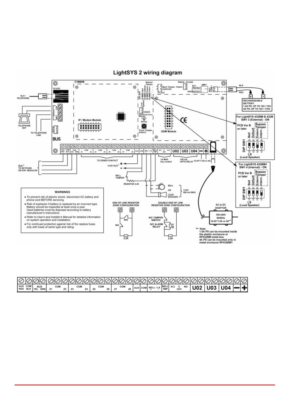
Figure 2-5: Main board wiring diagram
Main Board — Bus Connection
Figure 2-6: Main board terminal block
The set of four terminals on the left of the terminal block represent the expansion bus. These
terminals support the connection of keypads and expansion modules. The connections are
terminal‐to‐terminal with color‐coded wires, as follows:
AUX RED: +12V DC power BUS YEL: Yellow data
COM BLK: 0V common
BUS GRN: Green data
Connect any/all keypads and expanders necessary for the installation using the bus
connections. (Refer to the table of gauge sizes in Appendix A Technical Specifications.)