Installing bus devices – RISCO Group LightSYS 2 User Manual
Page 42
Installing Bus Devices
Page 42
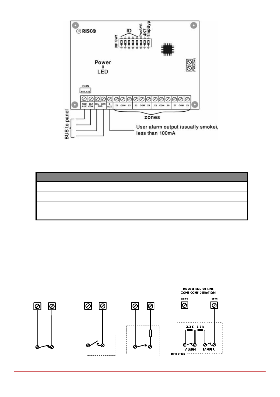
Figure 3-2: Zone Expander board and mounting diagrams
To install the 8‐zone expander
1. Set DIP switches as follows:
Switch
Description
Switch 1‐5
Defines the Zone Expander ID number.
Switch 6‐7
Not Applicable
Switch 8: Tamper bypass
Instead of a short between the TMP/COM
terminal block
2. Wire the zone expander to the bus
3. Wire the zones terminals as follows:
a. Connect up to eight hardwired zones, using twisted‐pair or 4‐conductor cable
wiring.
b. Connect each zone to the appropriate Zone (Z) terminal and its related COM
terminal. Each pair of zones shares a COM terminal. For example, Z1 and Z2
share a COM terminal, as do Z3 and Z4, and so on.
END OF LINE ZONE
(N.O CONTACT)
zone
com
ALARM
2.2
K
DETECTOR
NORMALLY OPEN ZONE
CONFIGURATION
ALARM
zone
com
DETECTOR
NORMALLY CLOSED
ZONE CONFIGURATION
ALARM
zone
com
DETECTOR
END OF LINE ZONE
(N.C CONTACT)
2.2
K
zone
com
ALARM
DETECTOR
DOUBLE END OF LINE
ZONE CONFIGURATION
com
2.2
K
ALARM
TAMPER
zone
2.2
K
DETECTOR