RISCO Group LightSYS 2 User Manual
Page 45
Installing Bus Devices
Page 45
Connect one (or more) normally open (NO) momentary‐action pushbutton
switches in a series between the TAMP and COM terminals in order to short‐
circuit these terminals while the cabinet door is closed.
Note:
It is not necessary to use a tamper switch if another module sharing the same
cabinet is equipped with one.
Do NOT use an End‐of‐Line Resistor in the tamper switch circuit.
If a tamper switch is not used, connect a wire jumper between the two terminals.
Wireless Expander
Up to two Wireless expanders (model WL432) can be assigned to the LightSYS2.
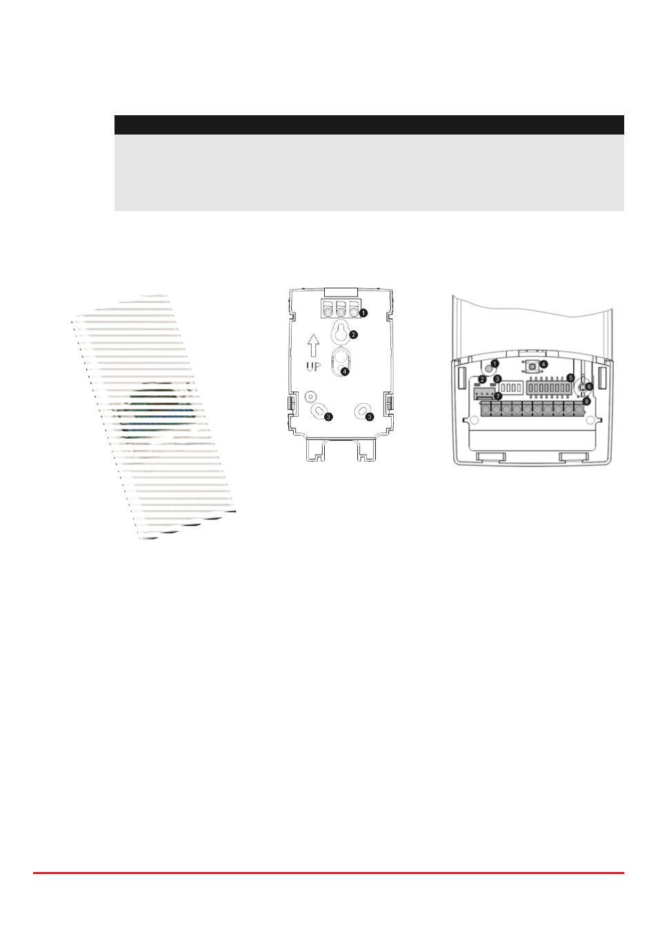
WL Expander Mounting
Bracket
1. Screw cap
2. Upper mounting hole
3. Lower mounting holes
(optional)
4. Wall tamper hole
1. Optional screw hole
(used to fasten front and
back covers)
2. Red LED
3. Green LED
4. Prog button
5. DIP switch
6. Box tamper
7. Bus Connector
8.
Terminal block
Figure 3-7: Wireless Expander
To install the wireless expander
1. Separate the mounting bracket from the main unit.
2. Use the mounting bracket as a marking template.
3. Tear off screw caps, as needed for covering front screw hole.
4. Mount the bracket to the wall.
5. Open the wireless expander front cover.
6. Set DIP switches as follows: