RISCO Group LightSYS 2 User Manual
Page 31
Mounting and Wiring
Page 31
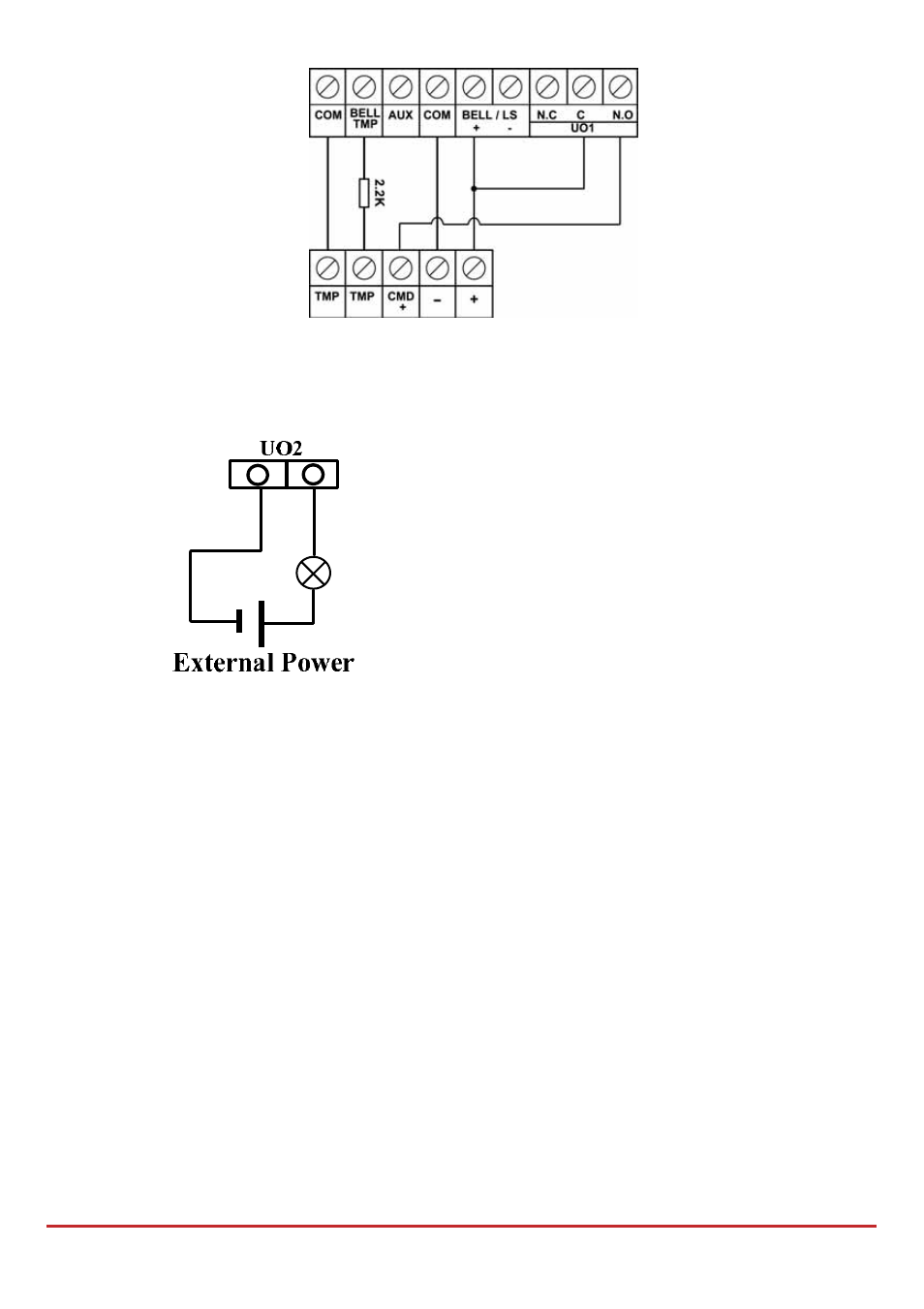
Figure 2-8: Wiring U01 for self-powered device
To wire Utility
Outputs 2‐4:
Connect the device to the UOʹs as illustrated below:
Back Tamper (Optional)
The back tamper switch is an optional feature that provides an extra safeguard. In the event
that the LightSYS2 is removed from the wall, the screw causes the perforated section of the
plastic and attached tamper mechanism metal plate to break and remain attached to the
wall. As a result, the back tamper switch is released and an alarm is generated. For this
feature to operate:
1. Slide the tamper mechanism (from the right) onto the placement struts and click
into place. The metal lip extends to the screw mounting hole.
2. When the LightSYS2 housing box is screw attached to the wall, also screw attach the
tamper hole and abutting tamper metal lip (to the mounting bracket you inserted in
step
2
on page 23)
3. Attach the tamper wires to PCB main board PLUG2 (see below, Figure 2‐9).
The back tamper switch is located on the rear side of the back panel and is constantly
depressed by the section shown in
Figure 2‐9