RISCO Group LightSYS 2 User Manual
Page 44
Installing Bus Devices
Page 44
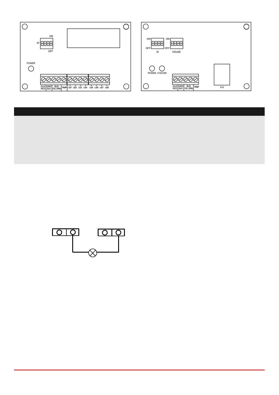
Figure 3-5: Utility Output Module E08
Figure 3-6: Utility Output Module X-10
Notes:
Outputs on module EO8:
Current consumption: 25 mA, typical / 30 mA, maximum;
Contacts; 12V Open Collector, Active Pull‐Down, 70 mA, maximum
Outputs on module EO4:
Current consumption 25 mA, typical / 140 mA, maximum;
Contact rating: 5 A / 24V DC.
To install the utility output expanderss:
1. Set the output expander ID using the ID DIP switches.
2. Wire the UO expander to the bus.
3. Connect the devices to the output terminals as follows:
a. UO4 – Relays (see Figure 2‐8 and Figure 3‐4)
b. UO8 – Open collectors:
UO1 UO2
AUX GND
c. X10:
i. Connect an RJ25 cable (4‐wire telephone cable) between the RJ11 connector
on the X‐10 module and the X‐10 transmitter.
ii.
Plug the X‐10 transmitter into the AC power.
iii. Plug the X‐10 receiver into the AC power close to the device that will be
operated.
iv.
Connect the X‐10 receiver to the device
4. Mount the Utility Output Expansion Modules in the main panel cabinet,
depending on space availability or in a separate cabinet (see Figure 3‐3) .
5. If the Utility Output expansion module is mounted in a separate cabinet you can
use the TAMP and COM terminal to tamper the cabinet, as follows: