Installing bus devices, Figure 3-9: 1.5a ps module, Figure 3-8: 3a ps module – RISCO Group LightSYS 2 User Manual
Page 46: Page 46
Installing Bus Devices
Page 46
Switch
Description
SW1‐ SW3
3 switches to set ID of the wireless expander.
SW4 – SW6
3 switches to set ID of the 2‐output expander.
SW7:
UO expander Enable/Disable
Off: Disable
On: Enable
SW8
Expander operational mode
Off : Bus mode
On: Stand alone mode
7. Wire the wireless expander to the bus.
8. Connect the devices to the outputs terminals (12VDC @ 1A max Dry Contact
Relays). See Figure 2‐8 and Figure 3‐4
9. Mount the wireless expander to the mounting bracket.
10. Close the mounting screw
11. Close the front cover. Use the screw cap you tore on Step 3 on the rear side.
Note:
For additional programming and configuration instructions, see 5IN1424 Wireless
Expander 432 Installation instructions
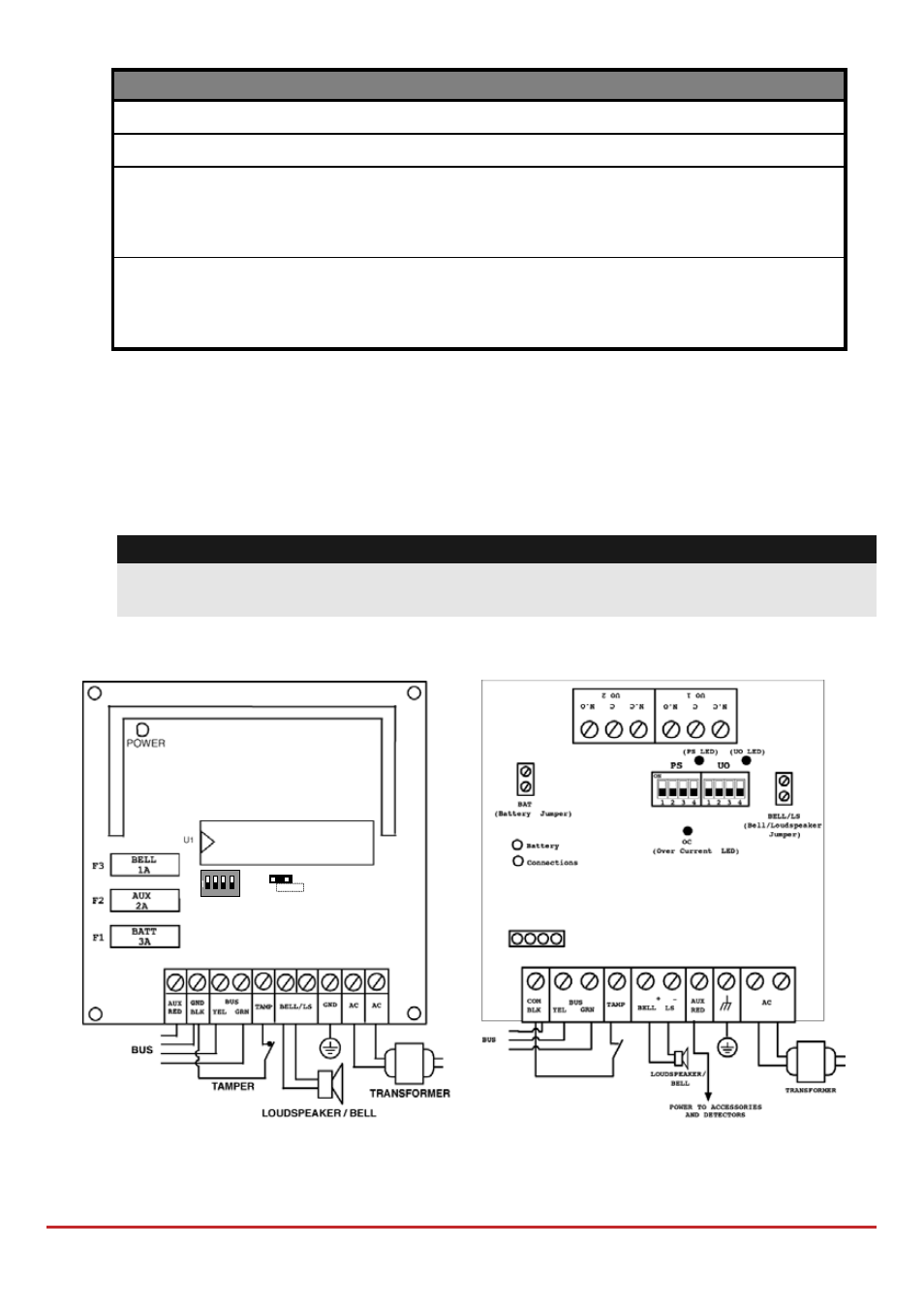
1.5 and 3A Switching Power Supply Expansion Modules
Figure 3-9: 1.5A PS Module
ON
1
2
3
4
ON
OFF
SW1
BELL
LS
Figure 3-8: 3A PS Module