RISCO Group LightSYS 2 User Manual
Page 36
Mounting and Wiring
Page 36
Main Unit DIP Switch and Jumper Setting
Plugs
Plug Description
Function
PLUG 1
Bus Connector
Bus 4 pin plug for easy connection to the bus
PLUG 2
Back Tamper
Used for the connection of the optional back tamper
PLUG 3
Telephone
Used for a local telephone connection (same as the
PHONE SET terminal)
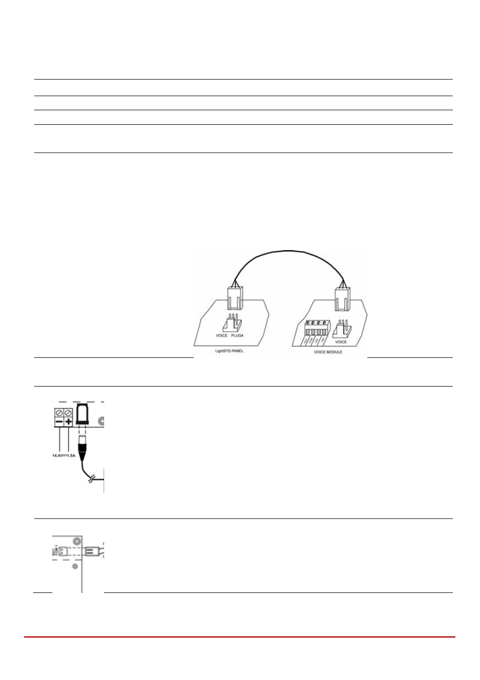
PLUG 4
Voice
Used to connect the Advanced Digital Voice
Module (RP432EV) to the LightSYS2.
Connect the Voice module to the VOICE connector
(PLUG 4) on the main panel via the supplied cable. This
connector transmits signals from the voice module to
the telephone line during remote communication and is
essential for normal operation of the voice module.
PLUG 5
RS‐232
Used for local communication with the configuration
software.
PLUG 6
Use this outlet for connection to the RISCO supplied
certified AC to DC adaptor.
Note: the Adaptor outgoing power cord can be cut for
the plug and attached to the supplied terminal block
fuse (See Figure 2‐3) as per your local wiring
requirements.
Additionally, input wiring can also be connected to
LightSYS2 through the neighboring (–) and (+) terminal
block connectors.
PLUG 7
Battery
Use this outlet to connect to the backup battery (not‐
supplied), of 12 volts and 7Ah