RISCO Group LightSYS 2 User Manual
Page 49
Installing Bus Devices
Page 49
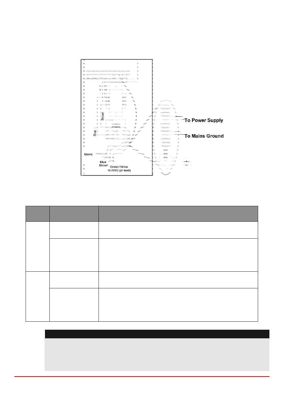
e. GROUND (Earth): Used to connect the GND terminal to the main box
ground pin (see illustration below). Use 16 AWG (at least).
f. AC: Used for connection of the AC terminals (see illustration below) to the
transformer outputs (16.5VAC/50 VA).
Figure
3-11: SMPS – AC & Ground Connection
7. Set the SMPS jumpers and the DIP switches as follows:
Mod-
ule
DIP switch
Description
Power
Supply
PS/SW1‐SW3
Used to set a unique ID number for the bus module for
communication purposes.
PS/SW4
Enables/disables Power Supply – LightSYS2
communication.
On (up): Communication enabled.
Off (down): Communication disabled
Utility
Output
UO/ SW1‐SW3
Used to set a unique bus ID number for the UO module
located on the SMPS board.
UO/SW4
Enables/disables UO module – LightSYS2
communication.
On (up): communication enabled.
Off (down): communication disabled
Note:
When PS/SW4, or UO/SW4 is Off, the ID number defined by SW1‐SW3 is not
recognized by the LightSYS2 and can be used for the connection of another
accessory of the same category. The UO/PS LED will flash since there is no
communication with the main panel.