RISCO Group LightSYS 2 User Manual
Page 43
Advertising
Installing Bus Devices
Page 43
4. Supply power to auxiliary devices. Refer to Wiring Auxiliary Devices, p. 29)
Note:
The RP432EZ8 enables to define the end‐of‐line resistance of its zones. Selection is done
through the Quick key programming:
.
5. Mount the zone expander in either of the LightSYS2 box left‐slots:
Figure 3-3: Zone Expander mounting location inside the LightSYS2 box
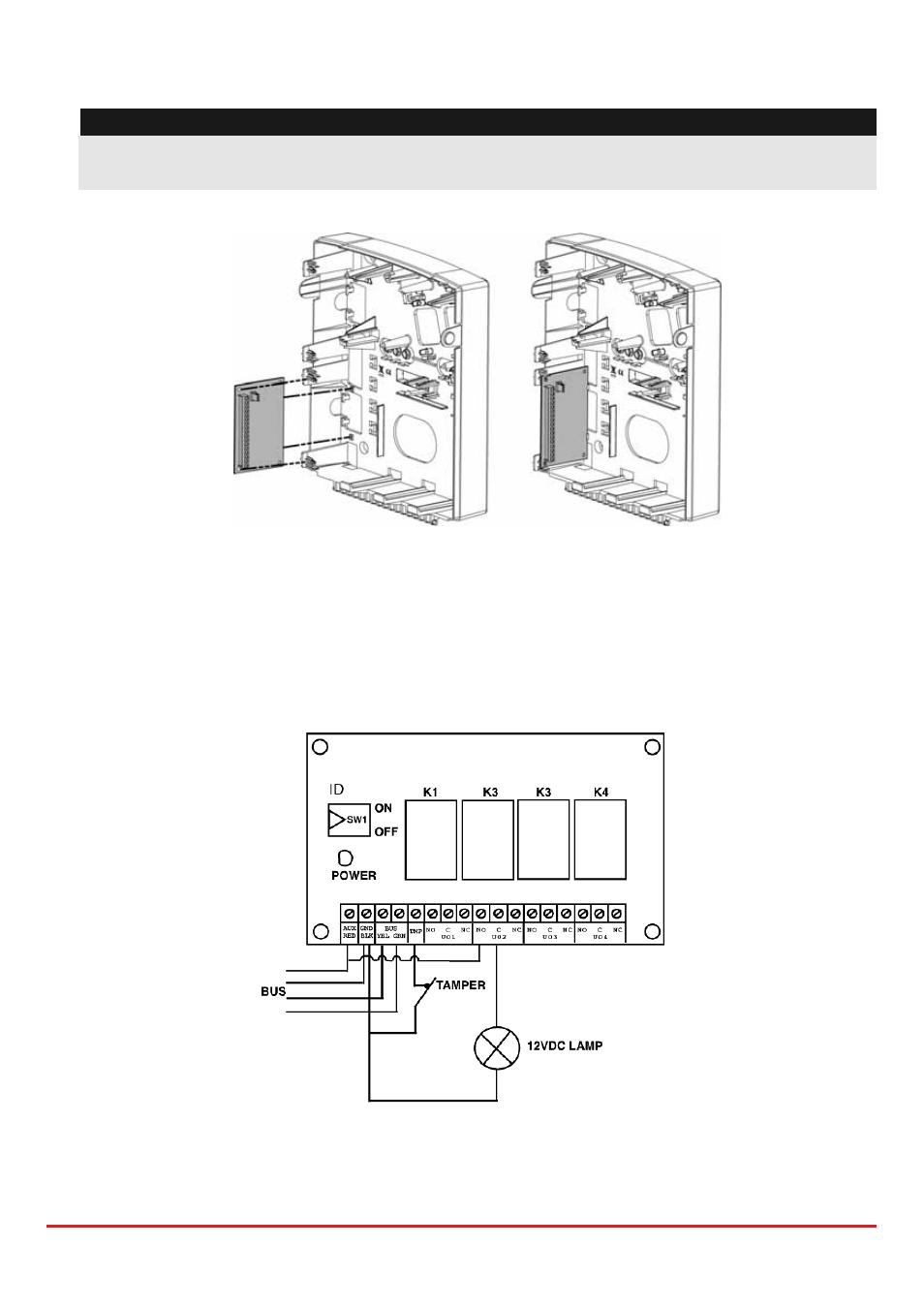
Utility Outputs
The LightSYS2 utility outputs support a variety of device activation, based on
periodicity or system event. As detailed in Chapter 4, Using the Installer Programming
Menus
Outputs , you can program customized device activation powerfully and
granularly.
Figure 3-4: Utility Output Module UO4 (Showing an Example of UO4 Wiring)
Advertising