RISCO Group LightSYS 2 User Manual
Page 51
Advertising
Installing Bus Devices
Page 51
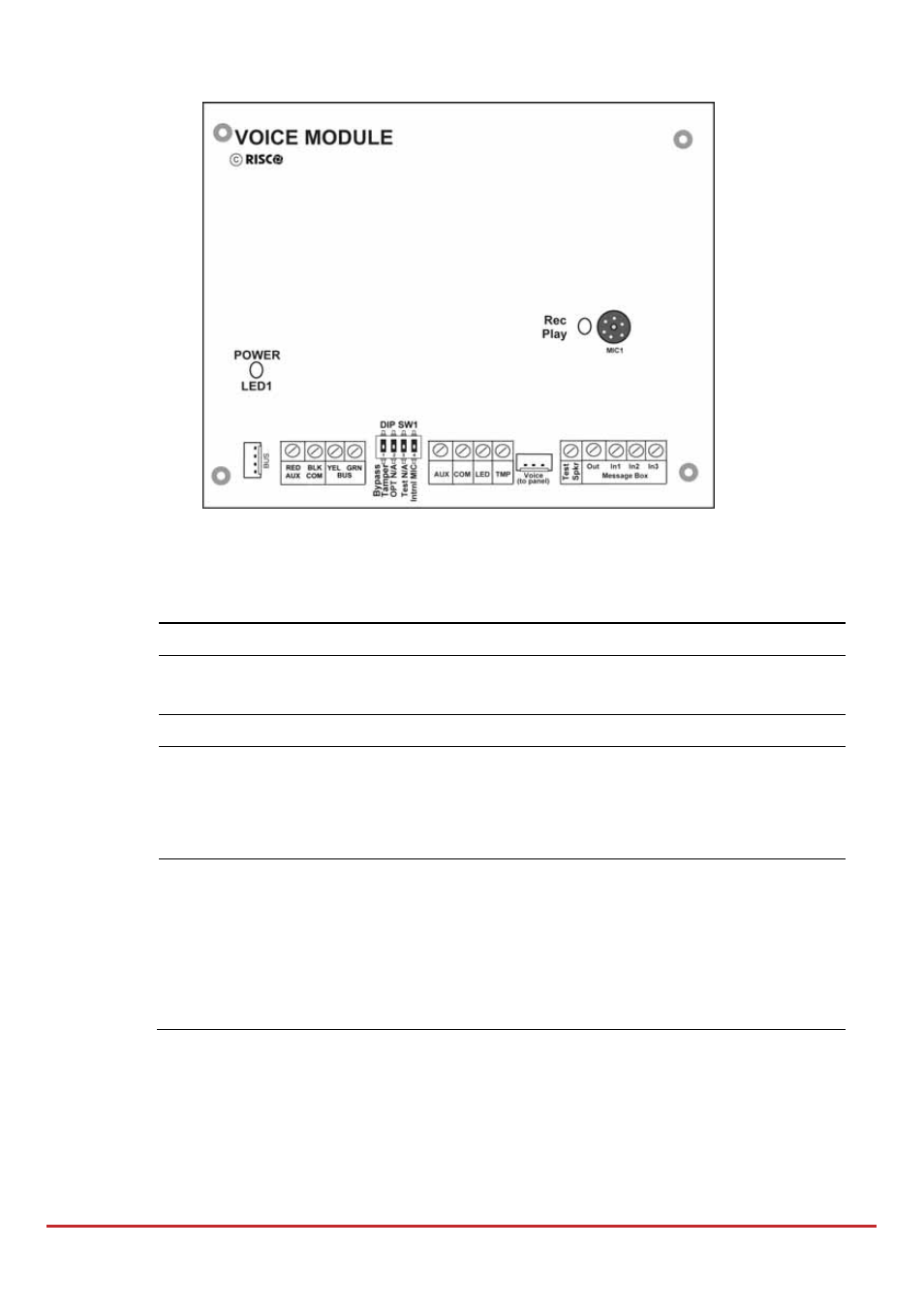
Digital Voice Module
Figure 3-12: Voice Module PCB
To mount the voice module:
1. Set the voice module DIP switches as follows:
Switch
Description
Usage
1
Bypass tamper
Instead of a short with the TMP/COM terminal
block
2
OPT
Not in use
3
Test
Connected in parallel to all output channels
and enables to listen to all played messages
using a speaker (at least 32 Ohm) connected
between the Test Spkr and COM terminals
4
Intern Mic
Select an external or internal microphone for
recording messages:
On: Recording messages from the microphone
located on the Voice module board.
Off: Recording messages from a microphone
located on Listen / Talk unit (IN1 terminal)
Advertising
See also other documents in the category RISCO Group Video surveillance systems:
- ProSYS 40 (48 pages)
- Risco Device Discovery (20 pages)
- NCache (24 pages)
- Reader AC500R11 (2 pages)
- axesplus® RDD (28 pages)
- ACMS (32 pages)
- ACMS (36 pages)
- Risco Services (68 pages)
- ACOS (28 pages)
- ACOS (88 pages)
- ACUS (28 pages)
- ACUS (56 pages)
- ACUS (525 pages)
- ACIS (111 pages)
- ACWS (36 pages)
- MAP Editor Installer (32 pages)
- Job Server Installer (32 pages)
- SafeWord OTP Server (36 pages)
- ProSYS – ACM (24 pages)
- axesplus® MAP Editor (68 pages)
- 2- Way iWAVE PIR /PET (2 pages)
- 2- Way iWAVE PIR /PET (2 pages)
- 2- Way iWAVE PIR /PET (2 pages)
- BWare 2W WL PIR (2 pages)
- BWare QUAD AM G3 (2 pages)
- BWare QUAD AM G3 (2 pages)
- BWare QUAD AM G3 (2 pages)
- BWare DT AM Grade 3 (2 pages)
- BWare G2 515DTGL (2 pages)
- BWare K-Band DT Grade 2 (2 pages)
- DIGI-SENSE 412DT PET (2 pages)
- DigiSense Digital Detector RK415DTQ (2 pages)
- Digi 412PT (2 pages)
- IR Beam 71 Outdoor Detector (2 pages)
- RK-308 (8 pages)
- ShockTec 600SG3 (2 pages)
- ShockTec 601SM (2 pages)
- ShockTec Plus G3 Digital Shock (2 pages)
- Vitron Plus G3 Acoustic Glass-Break Detector Vitron (2 pages)
- Vitron Acoustic Glass-Break Detector (2 pages)
- VitronPlus Acoustic Glass Break Detector (2 pages)
- WL Carbon Monoxide (2 pages)
- WL Flood Detector (2 pages)
- WL Gas Leak (2 pages)
- WL Shock & Contact Detector WL T62 (2 pages)