Chapter 3 installing bus devices – RISCO Group LightSYS 2 User Manual
Page 39
Installing Bus Devices
Page 39
Chapter 3 Installing Bus Devices
This chapter documents Installing Bus Expanders, p.41, including:
Keypads, page 41
Zone Expander, p. 41
Utility Outputs, p. 43
Wireless , p. 45
1.5 and 3A Switching Power Supply, p. 46
Sounders, p. 53
Connecting Bus Detectors, p. 54
Single Zone Expander, p. 55.
For detailed information of each device refer to the manual supplied with the product.
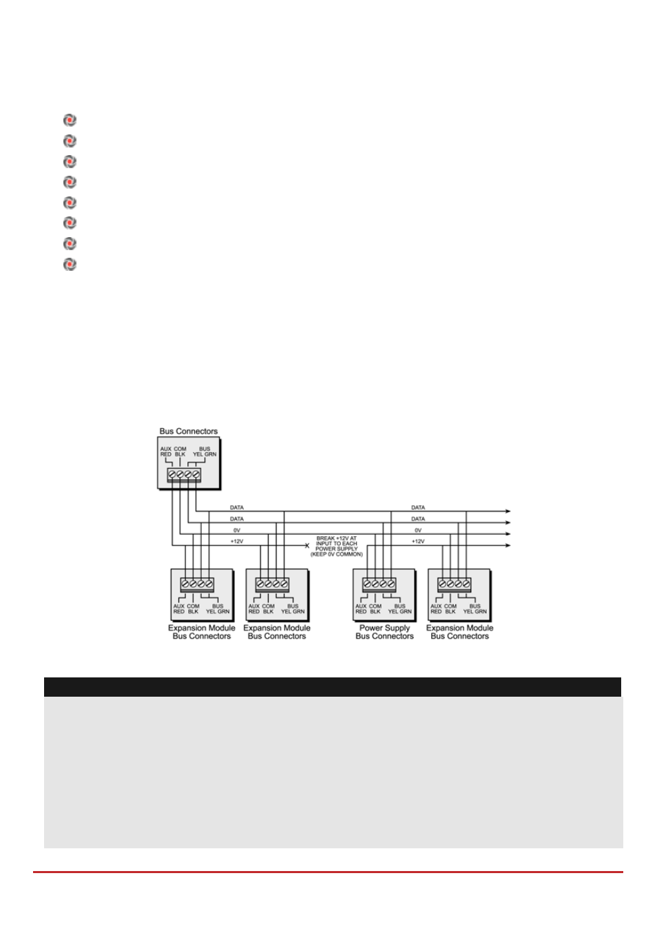
Bus connection
Each bus device has 4 bus terminals. The connections are terminal‐to‐terminal with color‐
coded wires, as follows:
AUX RED: +12V DC power BUS YEL: Yellow data
COM BLK: 0V common
BUS GRN: Green data
Connect each bus device necessary for the installation using the bus connections.
Figure 3-1: Terminal block bus connectors
Notes:
1. The parallel wiring system supports parallel connections from any point along the
wiring.
2. The maximum wire run permitted is 300 meters (1000 feet) for all legs of the bus.
3. In case of bus communication problems, connect two 2.2KΩ resistors, one at each end
of the data bus terminals, between the green and yellow wires.
4. If connecting remote power supplies, do NOT connect the red wire (+12v) between
the power supply unit and LightSYS2.
5.
For long cable runs, please use the correct cable as per Appendix A Technical Specifications