Bit decoding, Reset, Code error detect – Altera Stratix GX Transceiver User Manual
Page 124
5–12
Altera Corporation
Stratix GX Transceiver User Guide
January 2005
XAUI Mode Receiver Architecture
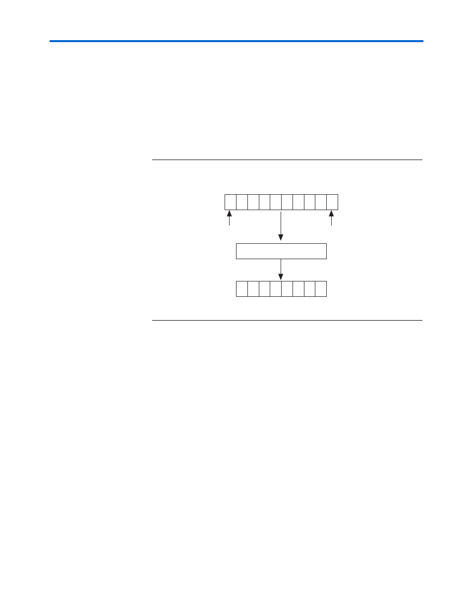
10-Bit Decoding
The 8B/10B decoder translates the 10-bit encode code into the 8-bit
equivalent data or control code. The 10-bit encoded code is received LSB
to MSB. The data that is received must be from the supported Dx.y or
Kx.y list. All 8B/10B control signals (disparity error, control detect, and
code error) are pipelined with the data in the Stratix GX receiver block
and are edge-aligned with the data.
diagrams the 10- to 8-bit
conversion.
Figure 5–9. 10-Bit to 8-Bit Conversion
Reset
The rxdigitalreset signal governs the reset condition of the 8B/10B
decoder. In reset, the disparity registers are cleared. Upon exiting reset,
the 8B/10B decoder can start with either a positive or negative disparity.
The decoder calculates the initial running disparity based on the first
valid code received.
The receiver block must be word-aligned after reset before the 8B/10B
decoder can decode valid data or control codes.
Code Error Detect
The rx_errdetect signal indicates when the code received contains an
error. This port is optional and if not in use, there is no way to detect
whether a code received is valid or not. The rx_errdetect goes high if
code that is received is invalid or if it contains a disparity error. If code
that is received is not part of the valid Dx.y or Kx.y list, the
rx_errdetect
signal goes high. This signal is aligned to the invalid
code word that is received at the FPGA logic array.
7
6
5
4
3
2
1
0
H
G
F
E
D
C
B
A
8b-10b conversion
7
6
5
4
3
2
1
0
9
8
g
f
i
e
d
c
b
a
j
h
LSB received
first
MSB received
last
Parallel Data
+ CTRL