Figure 5–13 – Altera Stratix GX Transceiver User Manual
Page 129
Altera Corporation
5–17
January 2005
Stratix GX Transceiver User Guide
XAUI Mode
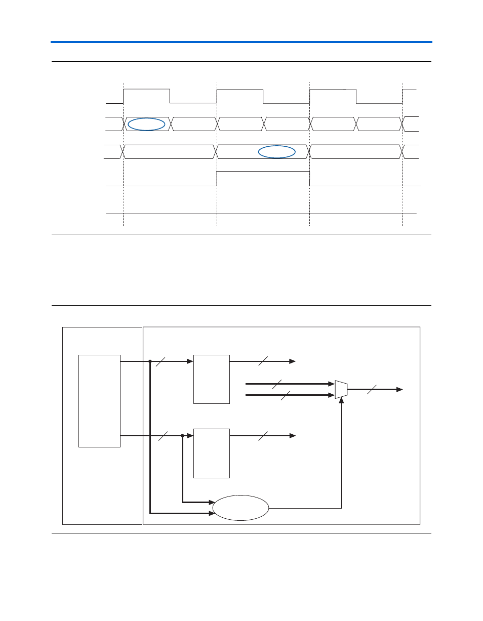
Figure 5–13. Receiver Byte Deserializer in 8/16-Bit Mode With Alignment Pattern in LSB
The logic array must include logic to perform byte position alignment
when the data enters the logic array, as seen in
. In this
example, the byte position selection logic determines the proper byte
position based on the pattern detect signal.
Figure 5–14. Receiver Byte Deserializer Data Recovery in Logic Array
xxxxxxxx01101111
inclk
data_out[15..0]
patterndetect[1]
11111000
10111100
11000110
data_in[7..0]
11110001
10101010
11001100
patterndetect[0]
B
C
D
E
F
A
BA
DC
10111100
11000110
11110001
10101010
Gigabit Transceiver Block
Logic Array
D
Q
D
Q
rx_out[17..10]
rx_out[7..0]
Byte Boundary
Selection Logic
rx_out_post[7..0]
rx_out_post[17..10]
{rx_out[7..0], rx_out_post[17..10]}
rx_out_post[17..0]
rx_out_align[17..0]
Phase
Compensation
FIFO
Buffer
8
8
8
8
16
8
8