Altera Stratix GX Transceiver User Manual
Page 128
5–16
Altera Corporation
Stratix GX Transceiver User Guide
January 2005
XAUI Mode Receiver Architecture
The byte deserializer outputs up to 26 bits, depending on the number of
bits that was passed to it. When the input includes data and control
signals, the data and the control signals are deserialized to include double
the data bits and 2 bits of each control signal, one for the MSB and one for
the LSB. This case is shown in the XAUI mode where the inputs to the
Byte Deserializer are datain[7..0], patterndetect, syncstatus,
disperr
, ctrldet, and errdet. These 13 input signals feeding the byte
deserializer and 26 output signals are fed to the FPGA logic array. The
signals are sent into the logic array as two 13-bit buses. The aggregate
bandwidth does not change by using the byte deserializer because the
logic array data width is doubled.
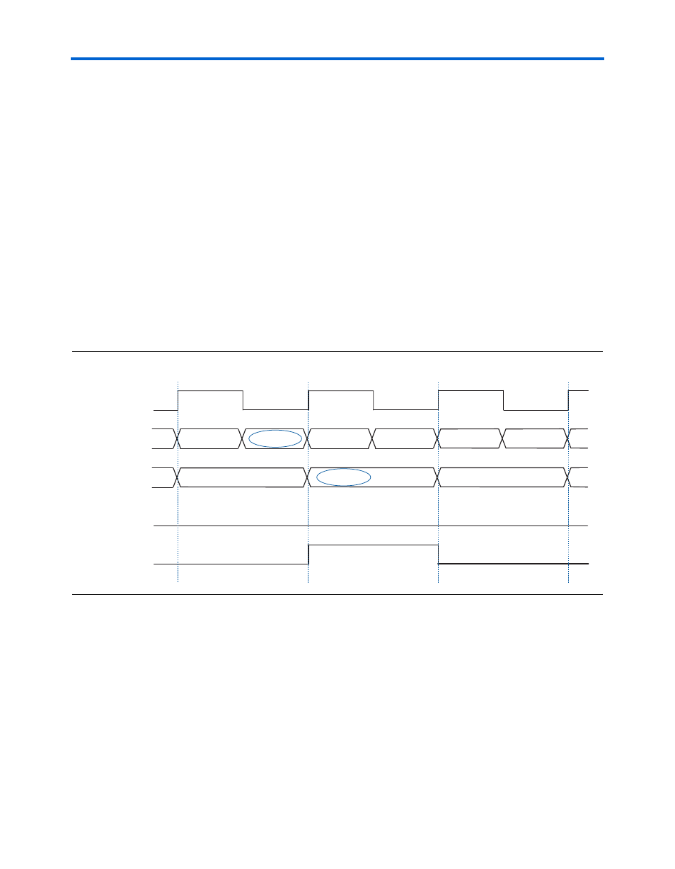
demonstrates input and output signals of the byte
deserializer when deserializing an 8-bit data input to 16 bits. In this case,
the alignment pattern A (10111100) is located in the MSB of the 16-bit
output, and this is reflected with patterndetect[1] going high. The
output of the byte deserializer is BA, DC, FE, and so on.
Figure 5–12. Receiver Byte Deserializer in 8/16-Bit Mode with Alignment Pattern in MSB
demonstrates the alternate case of the alignment pattern
found in the LSB of the 16-bit output. Correspondingly,
patterndetect[0]
goes high. In this case, the output is BA, DC, FE,
and so on.
xxxxxxxxxx
1010100000
1100011000
xxxxxxxxxxxxxxxxxxxx
inclk
data_in[7..0]
data_out[15..0]
1111000111
1010101010
1100110011
patterndetect[0]
patterndetect[1]
B
C
D
E
F
A
BA
DC
1010100000xxxxxxxxxx
1100011000
1111000111