Design examples, Top-level design (prbs.v), Design examples –7 – Altera Stratix GX Transceiver User Manual
Page 211
Altera Corporation
8–7
January 2005
Stratix GX Transceiver User Guide
Stratix GX Built-In Self Test (BIST)
Design
Examples
The purpose of these design examples are to show how to instantiate and
operate the various BIST modes in Stratix GX devices. The following
reference designs cover:
■
PRBS BIST generator and verification design
■
Incremental BIST generator and verification design
■
High-frequency transmitter generation design
■
Low-frequency transmitter generation design
■
Mixed-frequency transmitter generation design
Design 1: PRBS BIST Generator & Verification Design
This design shows how to use the BIST in PRBS 2
10
-1 mode. You can also
apply this design principle to the 2
8
-1 by changing the data-width mode,
comma, and word-alignment mode as listed in
.
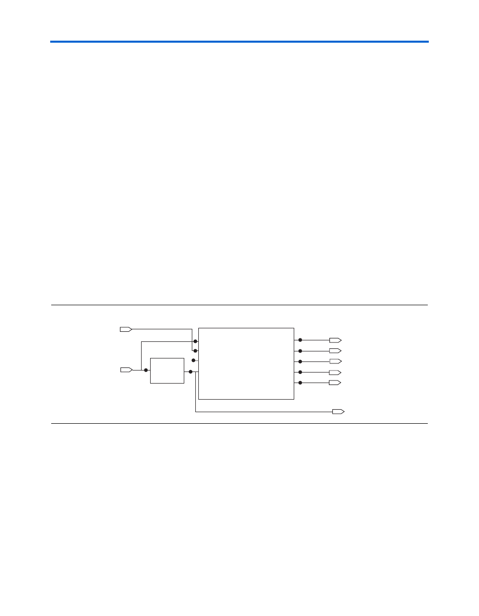
A useful circuit to include in the PRBS verifier is a self-timed reset
controller. This controller prevents bounce conditions that might occur
when an external switch is used. This design consists of a reset module
(reset.v) that periodically toggles the rxdigitalreset signal of the
altgxb
instantiation (PRBS_BIST.v).
shows a block diagram
of this design.
Figure 8–3. Block Diagram of the PRBS BIST Design
Top-Level Design (PRBS.v)
module PRBS(
inclk,
rx_in,
coreclk_out,
tx_out,
rx_bisterr,
rx_bistdone,
rx_clkout,
reset
);
inclk
rx_in
tx_out
coreclk_out
rx_clkout
rx_bistdone
rx_bisterr
PRBS_BIST
tx_out[0]
coreclk_out[0]
rx_clkout[0]
rx_bistdone[0]
rx_bisterr[0]
reset
PRBS_BIST_inst
inclk[0]
rx_in[0]
rx_slpbk[0]
rxdi
g
italreset[0]
reset_mod
clk
reset
reset_mod_inst