Altera Stratix GX Transceiver User Manual
Page 60
3–14
Altera Corporation
Stratix GX Transceiver User Guide
January 2005
Basic Mode Receiver Architecture
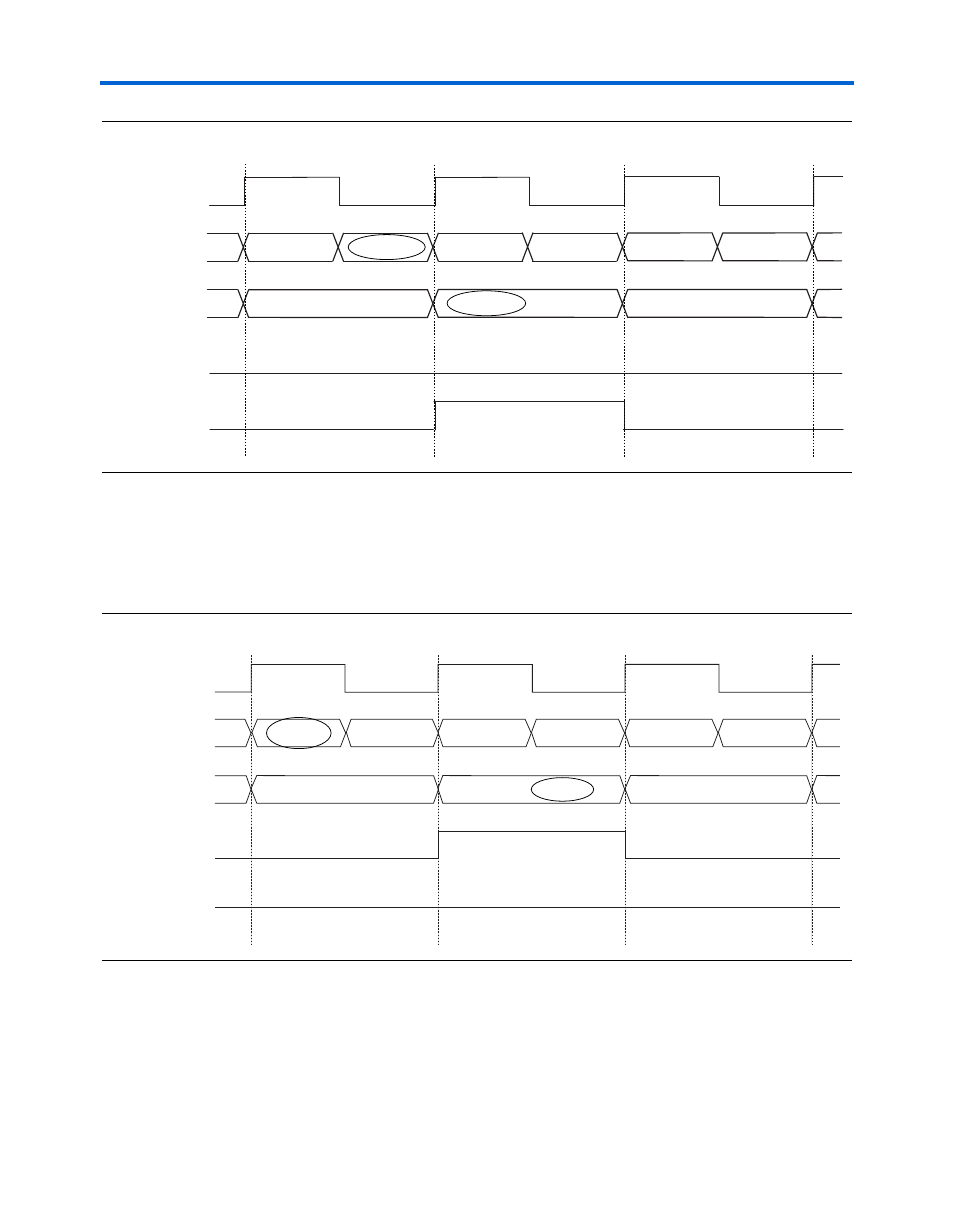
Figure 3–11. Receiver Byte Deserialzer in 10/20-Bit Mode With Alignment Pattern in MSB
demonstrates the alternate case of the alignment pattern
found in the LSB of the 20-bit output. Correspondingly,
patterndetect[0]
goes high. In this case, the output is BA, DC, FE,
and so on.
Figure 3–12. Receiver Byte Deserialzer in 10/20-Bit Mode With Alignment Pattern in LSB
You must implement logic for byte position alignment, if necessary, once
data enters the logic array, as seen in
. In this example, the byte
position selection logic determines the proper byte position based on the
pattern detect signal.
xxxxxxxxxx
1010100000
1100011000
xxxxxxxxxxxxxxxxxxxx
inclk
data_in[9..0]
data_out[19..0]
1111000111
1010101010
1100110011
patterndetect[0]
patterndetect[1]
A
B
C
D
E
X
AX
CB
1010100000xxxxxxxxxx
1100011000
1111000111
inclk
data_in[9..0]
data_out[19..0]
patterndetect[0]
patterndetect[1]
xxxxxxxxxxxxxxxxxxxx
1100011000
1111000111
1010100000
A
B
C
1010101010
D
1111100000
F
1100110011
E
11000110001010100000
BA
10101010101111000111
DC