Equalizer mode – Altera Stratix GX Transceiver User Manual
Page 29
Altera Corporation
2–11
January 2005
Stratix GX Transceiver User Guide
Stratix GX Analog Description
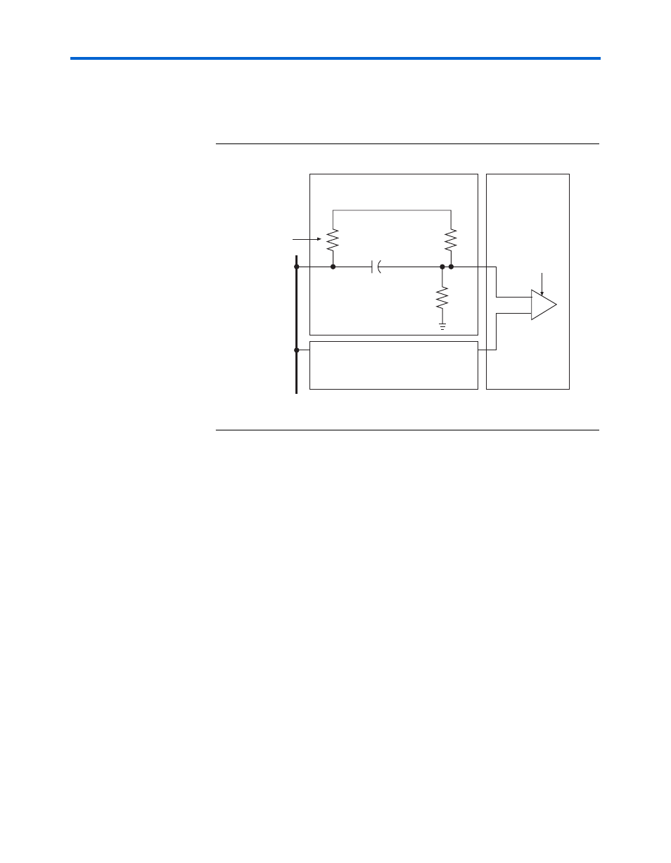
If external termination is used, the receiver must be externally terminated
and biased to 1.1 V.
shows an example of an external
termination and biasing circuit.
Figure 2–9. External Termination & Biasing Circuit
Enable Stratix GX-to-Stratix GX Receiver DC Coupling
You can configure the Stratix GX receiver buffers so that DC-coupled
Stratix GX-to-Stratix GX communication is possible. The Stratix GX
transmitter’s common-mode is typically around 750 mV, while the
receiver common mode by default is approximately 1.1 V. However, by
enabling DC coupling, the receiver common mode is biased to allow
interoperability with the Stratix GX transmitter.
Equalizer Mode
Stratix GX transceivers offer an equalization circuit in each receiver
channel to increase noise margins and help reduce the effects of high
frequency losses. The programmable equalizer compensates for
inter-symbol interference (ISI) and high frequency losses that distort the
signal and reduce the noise margin of the transmission medium by
equalizing the frequency response.
The transfer function of a transmission line can be represented in the
frequency domain as a low-pass filter. Any frequency components below
the –3-dB frequency pass through with minimal losses. Frequency
components that are greater than the –3-dB frequency are attenuated.
Transmission
Line
C1
R1/R2 = 1K
V
DD
× {R2/(R1 + R 2)} = 1.1 V
50/60/75-
Ω
Termination
Resistance
R1
R2
V
DD
Receiver External Termination
and Biasing
Stratix GX Device
Receiver External Termination
and Biasing
RXIP
RXIN
Receiver