Ppm frequency threshold detector, Receiver bandwidth type – Altera Stratix GX Transceiver User Manual
Page 33
Altera Corporation
2–15
January 2005
Stratix GX Transceiver User Guide
Stratix GX Analog Description
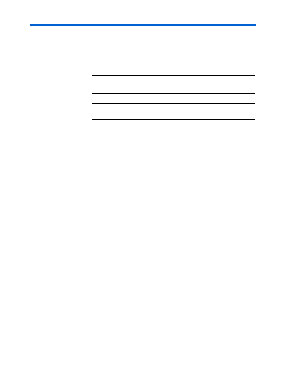
lists the possible multiplication values as a function of the
reference clock source to the receiver PLL.
reference clock (RX_CRUCLK) is directly fed from the source listed and
does not factor any pre-clock synthesis (that is, a Stratix GX PLL driving
a global clock used for the receiver PLL reference clock source).
You specify the data rate of the channel and receiver CRU clock period of
the receiver reference clock. The data rate divided by the input clock
period must equal one of the multiplication factors listed in
.
PPM Frequency Threshold Detector
The PPM frequency threshold detector senses whether the incoming
reference clock to the CRU and the PLL VCO of the CRU are within a
prescribed PPM tolerance range. Valid parameters are 125, 250, 500, or
1,000 PPM. The default parameter, if no assignments are made, is
1,000 PPM. The output of the PPM frequency threshold detector is one of
the variables that asserts the rx_freqlocked signal. Refer to
for more detail regarding the
rx_freqlocked
signal.
Receiver Bandwidth Type
The Stratix GX receiver PLL in the CRU offers a programmable
bandwidth setting. The bandwidth of a data recovery PLL is the measure
of its ability to track the input data and jitter. The bandwidth is
determined by the –3-dB frequency of the closed-loop gain of the PLL.
A higher bandwidth setting provides a faster lock time and tracks greater
jitter on the input data source, rx_in[], which passes it through the PLL.
This helps reject noise from the VCO and power supplies. A
low-bandwidth setting, on the other hand, filters out more
high-frequency data input jitter, but increases lock time.
Table 2–5. Multiplication Values as a Function of the Reference Clock
Source to the Receiver PLL
Receiver PLL Reference Clock Source
Multiplication Factors
Global clock, IO bus, general routing
8, 10, 16, 20
Inter-transceiver routing
4, 5, 8, 10, 16, 20
Dedicated local REFCLKB
4, 5, 8, 10, 16, 20
Low-speed transmitter PLL clock
(train CRU with transmitter PLL option)
2, 4, 5, 8, 10, 16, 20