Altera Stratix GX Transceiver User Manual
Page 284
9–58
Altera Corporation
Stratix GX Transceiver User Guide
January 2005
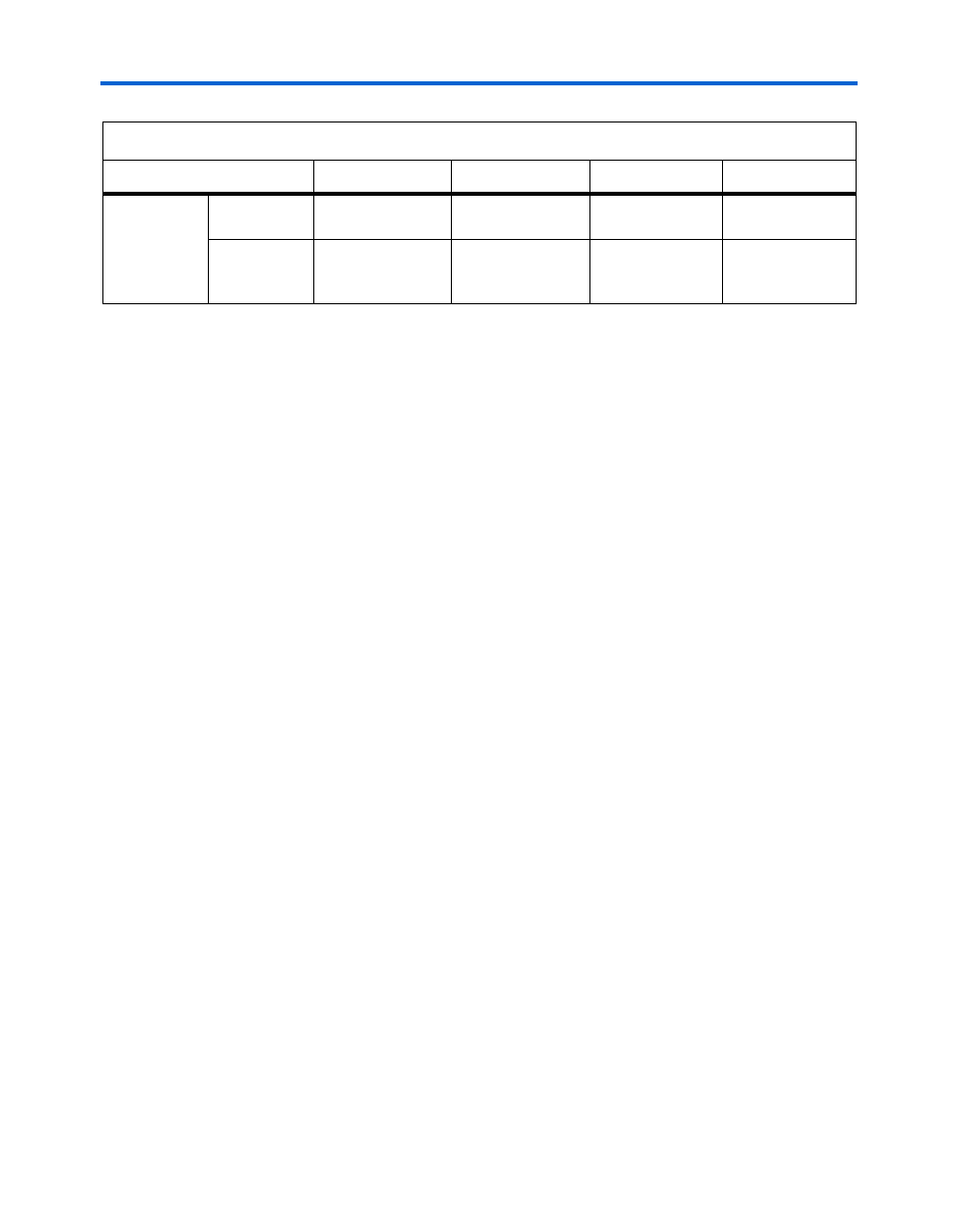
Power Down
PMA loop
back
Serial loop
back
toggle
Low
—
—
Reverse
serial loop
back
Transmitter
Receiver
—
—
(1)
Either leave these pins floating or connect n_leg to GXB_GND through a 10-k
Ω resistor and connect p_leg to
GXB_VCC
through a 10-k
Ω resistor to improve the device’s immunity to noise.
(2)
Either leave these pins floating or connect refclkb(+) to GXB_GND through a 10-k
Ω resistor and connect
refclkb(-)
to GXB_VCC through a 10-k
Ω resistor to improve the device’s immunity to noise.
(3)
Altera recommends driving the reference resistor pin low for the powered down transceiver block.
(4)
Transmitter output is tri-stated at the lowest V
OD
setting and is toggling at any other setting. However, the V
O D
is
80% of the selected V
O D
setting.
(5)
Receiver pin is pulled low internally. It must be either left floating or pulled low externally.
(6)
Only the 4-mA setting is supported for reverse serial loopback.
Table 9–2. I/O Pin States During Power-Down (Part 2 of 2)
Operation
Transmitter Pins
Receiver Pins
REFCLKB Pins
Rref Pin