Altera Stratix GX Transceiver User Manual
Page 91
Altera Corporation
4–9
January 2005
Stratix GX Transceiver User Guide
SONET Mode
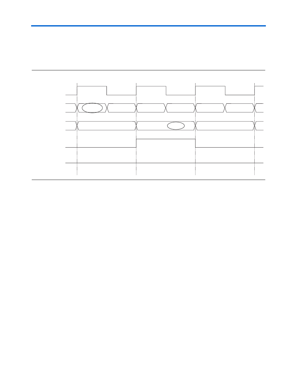
demonstrates the alternate case of the finishing alignment
pattern found in the LSB of the 16-bit output. Correspondingly
patterndetect[0]
goes high. In this case, the output is BA, DC, FE,
and so on.
Figure 4–7. Receiver Byte Deserializer in 8/16-Bit Mode with Finishing Alignment Pattern in LSB
If necessary, you might implement logic to perform byte position
alignment once data enters the logic array, as seen in
. In this
example, the byte position selection logic determines the proper byte
position based on the pattern detect signal.
inclk
data_in[7..0]
data_out[15..0]
patterndetect[0]
patterndetect[1]
xxxxxxxx01101111
11000110
11110001
00010100
A
B
C
10101010
D
11111000
F
11001100
E
11000110 00010100
BA
10101010 11110001
DC