Altera Stratix GX Transceiver User Manual
Page 89
Altera Corporation
4–7
January 2005
Stratix GX Transceiver User Guide
SONET Mode
comma, the rx_patterndetect[] signal is asserted for one clock
cycle. You must implement the logic in the device logic array to control
the bit-slip circuitry.
This scheme is useful if the comma changes dynamically when the
Stratix GX device is in user mode. Because the controller is implemented
in the logic array, a custom controller can be built to dynamically change
the comma without needing to reprogram the Stratix GX device. The
pattern detect circuitry matches only the pattern that is specified in the
MegaWizard Plug-In Manager and is not dynamically adjustable.
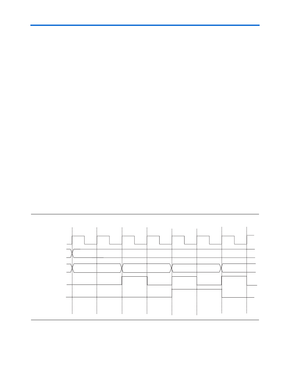
shows an example of how the word aligner signals interact in
the manual bit-slip alignment mode. In this example, 8'b00111100 is
specified as the comma, and an 8'b11110000 value is held at the rx_in
port. Every rising edge on the rx_bitslip port causes the
rx_word_align_out
data to shift one bit from the MSB to the LSB. At
time n+2, the 8'b11110000 data is shifted to a value of 8'b01111000.
At this state the rx_patterndetect is held low, because the specified
comma does not exist in the current word boundary. The rx_bitslip is
disabled at time n+3 and re-enabled at time n+4. The output of the
rx_word_align_out
now matches the specified comma, so the
rx_patterndetect
is asserted for one clock cycle. At time n+5, the
rx_patterndetect
is still asserted because the comma still exists in the
current word boundary. Finally, at time n+6, the rx_word_align_out
boundary is shifted again and the rx_patterndetect signal is
deasserted to signify that the word boundary does not contain the
comma.
Figure 4–5. Word Aligner Symbols Interacting in Manual Bit-Slip Mode
rx_recovclockout
rx_bitslip
rx_patterndetect
rx_word_align_out
11110000
01111000
00011110
n
n+1
n+2
n+3
n+4
n+5
n+6
rx_in
11110000
00111100