Reverse serial loopback, Reverse serial loopback –3 – Altera Stratix GX Transceiver User Manual
Page 203
Altera Corporation
7–3
January 2005
Stratix GX Transceiver User Guide
Loopback Modes
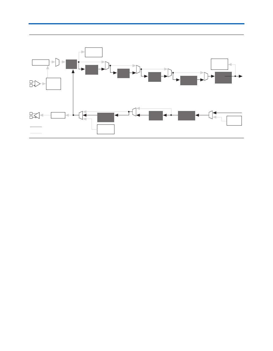
Figure 7–2. Stratix GX Block in Parallel Loopback Mode
Reverse Serial
Loopback
shows the data path for reverse serial loopback. Data comes in
from the rx_in ports in the receiver. The data is then fed through the
CDR block in serial form directly to the tx_out ports in the transmitter
block.
Reverse serial loopback is enabled for all channels through the software
or is dynamically enabled on a channel-by-channel basis using the
tx_srlpbk
port. When using reverse serial loopback, the V
OD
must be
400mV.
When tx_srlpbk is high, all blocks that are active when the signal is low
are still active. The reverse serial loopback is enabled but the logic array
is still seeing data.
Reverse serial loopback is often implemented when using a Bit Error Rate
Tester (BERT).
Clock
Recovery
Unit
Word
Aligner
BIST PRBS
Verifier
BIST
Incremental
Verifier
Channel
Aligner
Rate
Matcher
BIST
Generator
Byte
Deserializer
Phase
Compensation
FIFO
Phase
Compensation
FIFO
Byte
Serializer
Serializer
BIST PRBS
Generator
8B/10B
Encoder
8B/10B
Decoder
Deserializer
Non-Active Path
Active Path