Clock synthesis, Figure 2–10 – Altera Stratix GX Transceiver User Manual
Page 31
Altera Corporation
2–13
January 2005
Stratix GX Transceiver User Guide
Stratix GX Analog Description
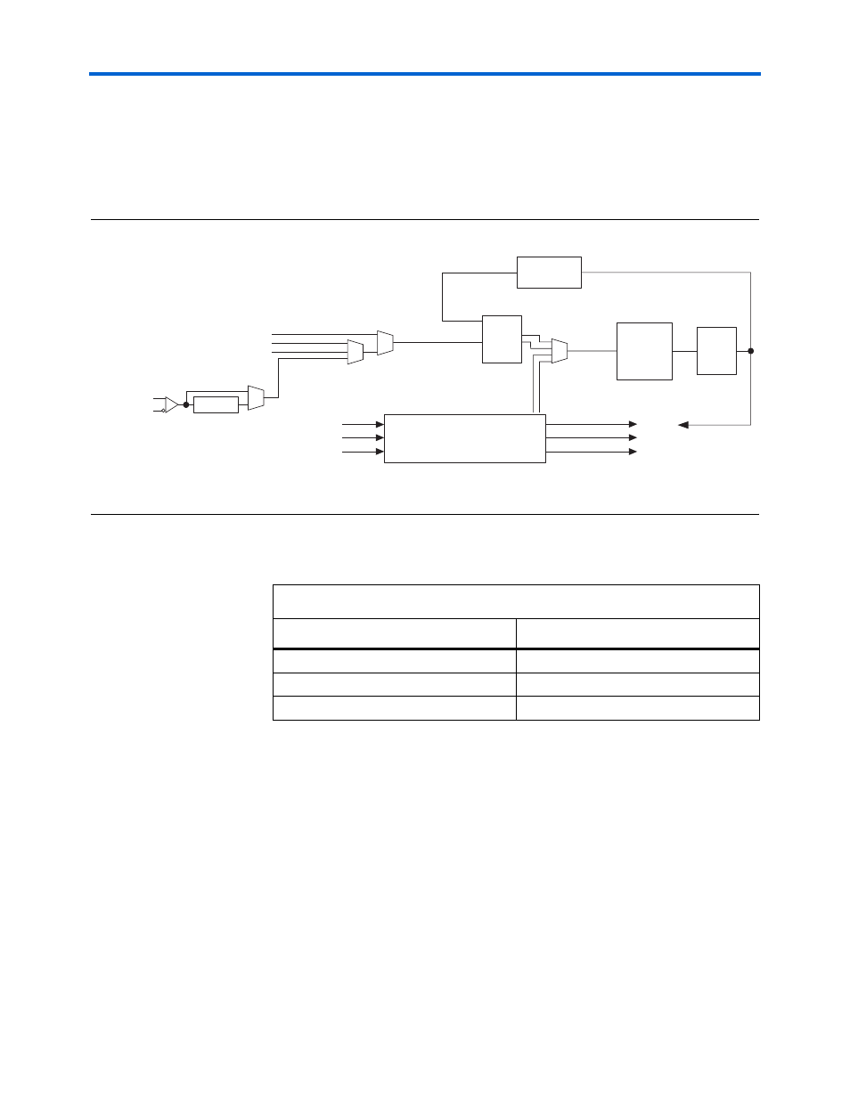
The receiver PLL contains an optional loss-of-lock indicator signal
(rx_locked) that indicates when the receiver PLL is not locked to the
reference clock. The rx_locked signal is active low. A low signal
indicates that the PLL is locked to a reference clock; a high signal indicates
that the PLL is not locked to the reference clock.
Figure 2–10. Receiver PLL Block Diagram
Note to
(1)
m = 8, 10, 16, or 20.
lists some of the clock recovery unit specifications.
Clock Synthesis
The maximum input frequency of the PFD of the receiver PLL is
325 MHz. To achieve reference clock frequency above this limit, the
Quartus II software enables the divide by 2 pre-divider on the dedicated
local REFCLKB path. This divides the reference clock frequency by a factor
of 2 and then the /m factor compensates the frequency difference. For
example, given a data rate of 2,488 Mbps with a reference clock of
622 MHz, the reference clock must be assigned to the REFCLKB port,
RX_CRUCLK
CP+LF
Up
Down
VCO
÷
m
RX_IN
Hi
g
h Speed RCVD_CLK
Low Speed RCVD_CLK
Global Clks, I/O Bus, Gen Routin
g
Inter Transceiver Block Routin
g
Dedicated Local
REFCLKB
Down
Up
rx_locktorefclk
rx_rlv[ ]
rx_locktodata
Low speed TX_PLL_CLK
÷
2
Clock Recovery Unit (CRU)
PFD
(1)
Table 2–4. Clock Recovery Unit Specifications
Parameter
Specification
Input reference frequency range
25 MHz to 650 MHz
Data rate support
500 Mbps to 3.1875 Gbps
Multiplication factor (W)
2, 4, 5, 8, 10, 16, or 20
Note to
:
(1)
Multiplication factors 2, 4, and 5 can only be achieved with the use of the pre-
divider on the REFCLKB port or if the CRU is trained with the low speed clock
from the transmitter PLL.