Altera Stratix GX Transceiver User Manual
Page 143
Altera Corporation
5–31
January 2005
Stratix GX Transceiver User Guide
XAUI Mode
Another multi-transceiver block issue is the selection of the dedicated
refclkb
pin. Stratix GX channels are arranged in banks of four, which
are called transceiver blocks. Each transceiver block has the ability to
share a common reference clock through the Inter-Transceiver (IQ) lines.
You can reduce the Stratix GX logic array clock usage by using the IQ
lines. The IQ lines are used when a refclkb input port from one
transceiver block or channel drives any other transceiver blocks or
channels. The IQ line usage is determined automatically by the Quartus II
software.
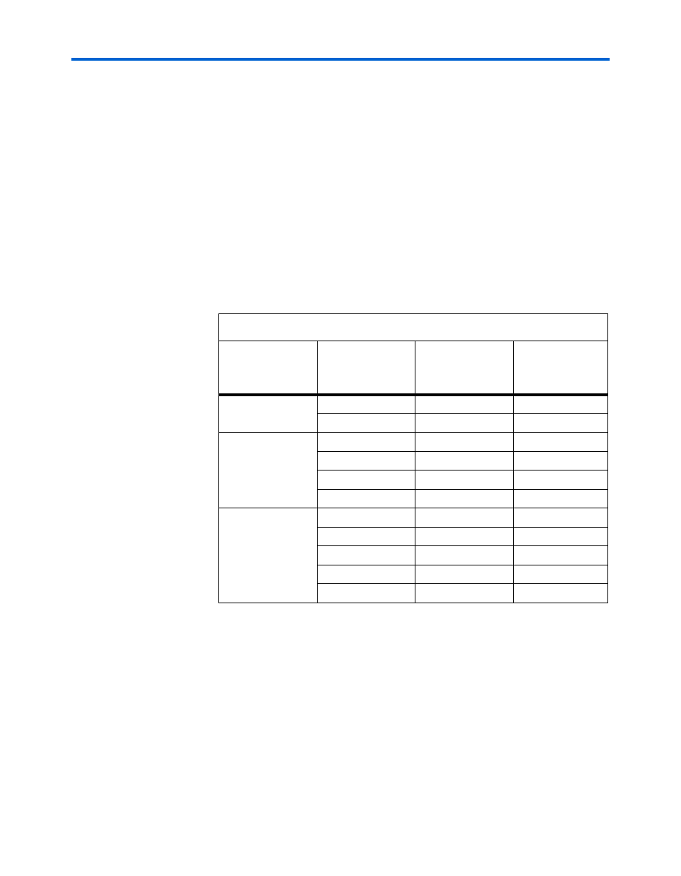
When determining the location of refclkb pins, consider what is fed by
the pin you select.
shows the available IQ lines and which
transceiver blocks are driven by refclkb. This information is based on
the number of transceiver channels in the Stratix GX device.
shows the transceiver routing with respect to Inter-
Transceiver lines. This information is vital when placing refclkb pins.
(When placing refclkb pins, see
for information about analog reads and refclkb pin usage
constraints.) For example, if a refclkb pin is required to feed a
transmitter PLL using an IQ line, the refclkb pin cannot be in
transceiver block 1, because IQ2 only feeds the receiver PLLs.
Table 5–6. REFCLKB to Inter-Transceiver Line connections
Channel Density
REFCLKB in
Transceiver Block
Number
Channels in
Transceiver Block
IQ Line Driven by
REFCLKB
8 channels
(EP1SGX10)
0
[3:0]
IQ2
1
[7:4]
IQ0
16 channels
(EP1SGX25)
0
[3:0]
N/A
1
[7:4]
IQ2
2
[11:8]
IQ0
3
[15:12]
IQ1
20 channels
(EP1SGX40)
0
[3:0]
N/A
1
[7:4]
IQ2
2
[11:8]
IQ0
3
[15:12]
IQ1
4
[19:16]
N/A