Deserializer (serial-to-parallel converter) – Altera Stratix GX Transceiver User Manual
Page 37
Altera Corporation
2–19
January 2005
Stratix GX Transceiver User Guide
Stratix GX Analog Description
If the data width is 8 or 16, set the legal run length threshold values within
the range of 4 to 128 UI in multiples of four. If the data width is 10 or 20,
or if using 8b10b, set the legal run length threshold values within the
range of 5 to 160 UI in multiples of five.
1
See the Stratix GX FPGA Family data sheet to verify the
guaranteed maximum run length.
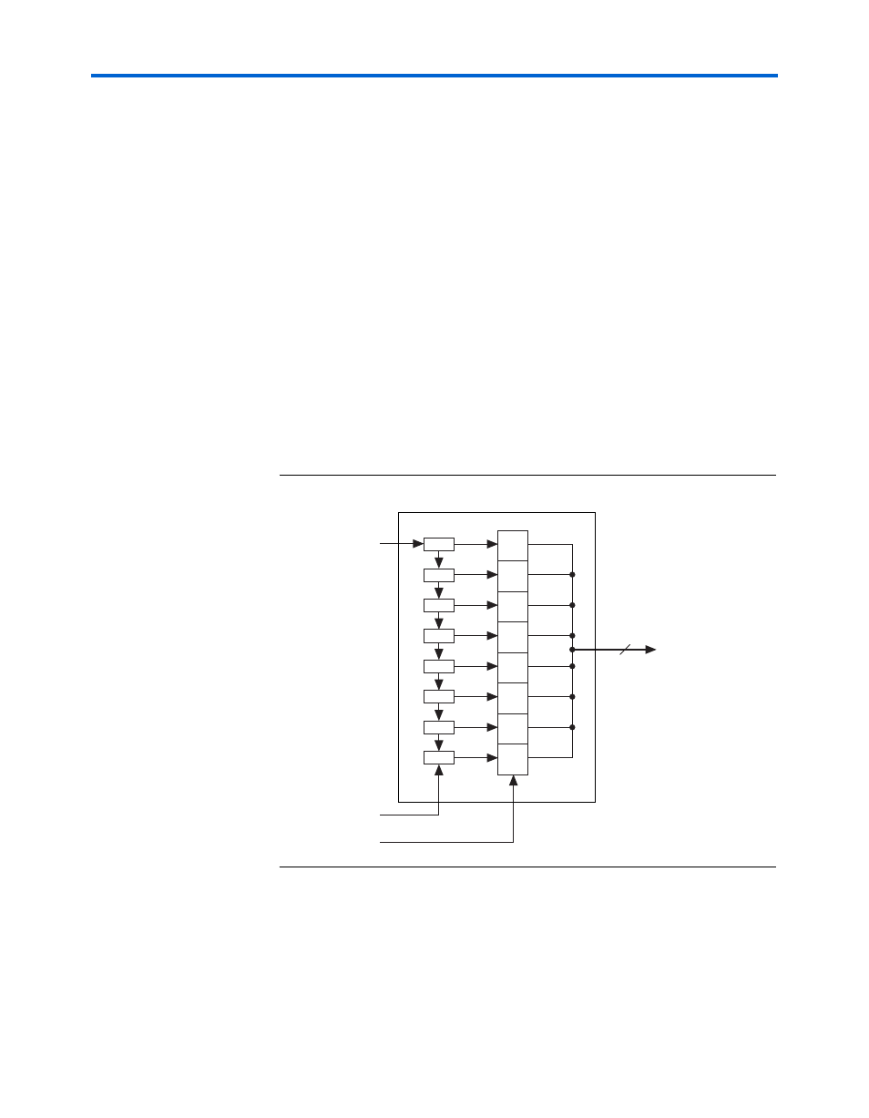
Deserializer (Serial-to-Parallel Converter)
The deserializer converts incoming high-speed serial data streams to
either 8- or 10-bit-wide parallel data synchronized to the recovered clock
of the CRU. The deserializer drives the parallel data to the pattern
detector and word aligner, as shown in
. The data rate of the
deserializer output bus is the input data rate divided by the width of the
output data bus. For example, for a 10-bit bus and a serial input data rate
of 2.5 Gbps, the parallel data rate is 2500/10 or 250 MHz. The first bit into
the deserializer is the LSB of the data bus out of the deserializer.
Figure 2–11. Deserializer Block Diagram
shows the serial bit order of the deserializer input and the
parallel data out of the deserializer.
1
The serial data is received LSB to MSB.
D7
D6
D5
D4
D3
D2
D1
D0
D7
D6
D5
D4
D3
D2
D1
D0
8
Parallel Data Out
(To Word Aligner)
Low-speed
Parallel Clock
High-speed
Serial Clock
Serial Data In
(From CRU)
Deserializer