Results – Altera Stratix GX Transceiver User Manual
Page 215
Altera Corporation
8–11
January 2005
Stratix GX Transceiver User Guide
Stratix GX Built-In Self Test (BIST)
altgxb_component.data_rate = 3125,
altgxb_component.align_pattern = "P1111111111",
altgxb_component.use_rx_cruclk = "OFF",
altgxb_component.number_of_quads = 1;
endmodule
Results
A quick method for verifying whether the BIST verification passes or fails
is to use the SignalTap
®
II logic analyzer in the Quartus
®
II software. Refer
to Application Note 280: Design Verification Using the SignalTap II Logic
Analyzer for more information on using the SignalTap II logic analyzer.
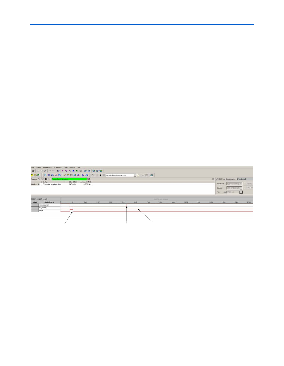
The SignalTap II logic analyzer trigger is set to the falling edge of the reset
output signal.
is a screen shot of the SignalTap II logic analyzer
results for this PRBS BIST test.
Figure 8–4. SignalTap II Logic Analyzer Results for PRBS BIST Test Design
Design 2: Incremental BIST Generator & Verification Design
This design is similar to the PRBS BIST generator and verification design,
except the altgxb megafunction is configured to the incremental BIST
mode. Refer to the design for information on the ports and parameters
required for altgxb in this mode.
As in the PRBS design, a useful circuit to include in the PRBS verifier is a
self-timed reset controller. This controller prevents bounce conditions
that might occur when an external switch is used. This design consists of
a reset module (reset.v) that periodically toggles the
rxdigitalreset
signal of the altgxb instantiation
shows a block diagram of this
design.
(1)
(2)
(3)
Resets the Verifier
rx_bistdone signifies that
the verification cycle is complete
rx_bisterr remains low, signifying
no bit errors