Chart in, Figure 9–11 – Altera Stratix GX Transceiver User Manual
Page 259
Altera Corporation
9–33
January 2005
Stratix GX Transceiver User Guide
Reset Control & Power Down
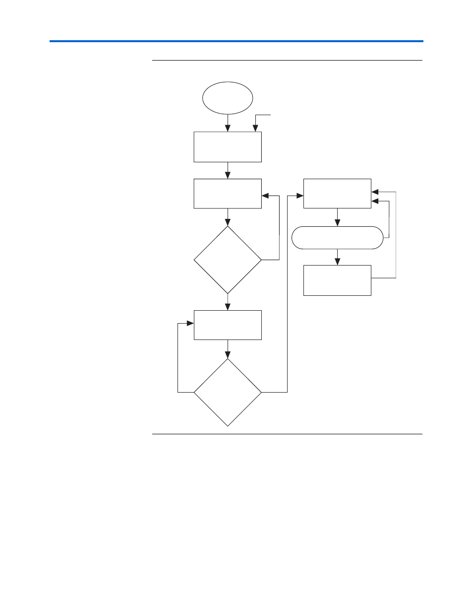
Figure 9–11. Receiver Reset Sequence
The waveform in
shows the functionality of the receiver reset
. The rx_analogreset signal is pulsed.
After the CRU has transitioned to locking-to-data from locking to the
reference clock, the rx_freqlocked signal is asserted, which allows a
reset sequence to transition into a wait state, where a timer is loaded with
T ms. When the timer counts down the value, it signifies that rx_clkout
is stable. The reset controller then deasserts the rx_digital reset, which
completes the reset sequence.
Start
pll_areset = high
rxanologreset = high
rxdigitalreset = high
pll_areset = low
rxanalogreset = low
rxdigitalreset = high
rxfreqlocked = high
pll_areset = low
rxanalogreset = low
rxdigitalreset = high
YES
NO
async_reset or sync_reset
pll_areset = low
rxanalogreset = low
rxdigitalreset = low
receive_digitalreset = high
pll_areset = low
rxanalogreset = low
rxdigitalreset = high
YES
NO
YES
waitstate_timer = 0
NO