Altera Stratix GX Transceiver User Manual
Page 247
Altera Corporation
9–21
January 2005
Stratix GX Transceiver User Guide
Reset Control & Power Down
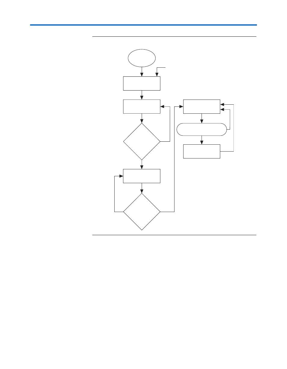
Figure 9–8. Receiver Reset Sequence
The waveform in
shows the functionality of the receiver reset
sequence shown in
. The rx_analogreset signal is pulsed.
After the CRU has transitioned to locking to data from locking to the
reference clock, the rx_freqlocked signal is asserted, which allows the
reset sequence to transition into a wait state, where a timer is loaded with
T ms. When the timer counts down the value, it signifies that rx_clkout
is stable. The reset controller then deasserts the rx_digital reset, which
completes the reset sequence. You should be able to monitor the BER (for
example, a synchronization state machine based on the Stratix GX
transceiver data) to determine whether the system is initialized and
working properly.
f
See the Stratix GX FPGA Family data sheet for the value of
Trx_freqlock2phaselock
.
Start
rxanologreset = high
rxdigitalreset = high
rxanalogreset = low
rxdigitalreset = high
rxfreqlocked = high
rxanalogreset = low
rxdigitalreset = high
YES
NO
pll_areset or sync_reset
rxanalogreset = low
rxdigitalreset = low
receive_digitalreset = high
rxanalogreset = low
rxdigitalreset = high
YES
NO
YES
waitstate_timer = 0
NO