Altera Stratix GX Transceiver User Manual
Page 198
6–44
Altera Corporation
Stratix GX Transceiver User Guide
January 2005
Design Example
altgxb_component.preemphasis_ctrl_setting = 0,
altgxb_component.loopback_mode = "SLB",
altgxb_component.use_channel_align = "OFF",
altgxb_component.intended_device_family =
"Stratix GX",
altgxb_component.use_equalizer_ctrl_signal =
"OFF",
altgxb_component.rx_enable_dc_coupling = "OFF",
altgxb_component.run_length_enable = "OFF",
altgxb_component.pll_use_dc_coupling = "OFF",
altgxb_component.operation_mode = "DUPLEX",
altgxb_component.use_8b_10b_mode = "ON",
altgxb_component.use_rx_clkout = "OFF",
altgxb_component.data_rate_remainder = 0,
altgxb_component.data_rate = 1280,
altgxb_component.align_pattern = "P0101111100",
altgxb_component.use_rx_cruclk = "OFF",
altgxb_component.number_of_quads = 1;
endmodule
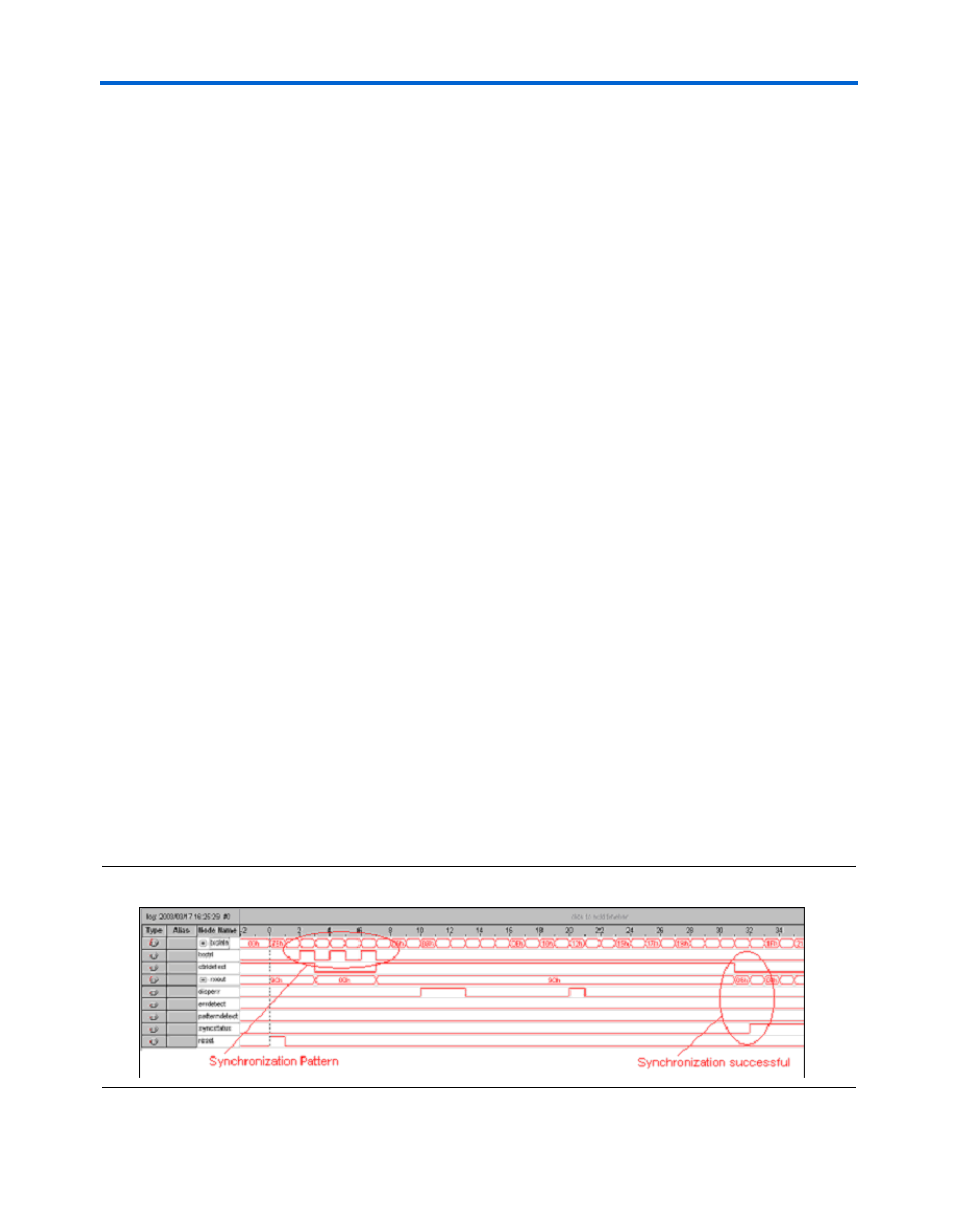
Simulation Waveform & Hardware Verification Results
show the complete synchronization sequence from
the transmitter to the receiver for the SignalTap
®
II logic analyzer and the
Quartus II software, respectively. The GigE duplex channel is configured
in a serial loopback mode. The synchronization pattern is sent by the
transmitter. The receiver sends a K28.4 character (8’ b9C + ctrl) until
synchronization is achieved. Although any odd number of valid /Dx.y/
codes is supported between each /K28.5/ code, one /Dx.y/ is shown in
this example.
The 8’h00 shown on the rx_out bus results from the reset pulse when
the pipelined registers are reset in the receiver block.
There is good correlation between the SignalTap II logic analyzer results
and the Quartus II software simulation.
Figure 6–34. GigE Synchronization Sequence SignalTap II Results