Programmable receiver termination – Altera Stratix GX Transceiver User Manual
Page 28
2–10
Altera Corporation
Stratix GX Transceiver User Guide
January 2005
Receiver Analog
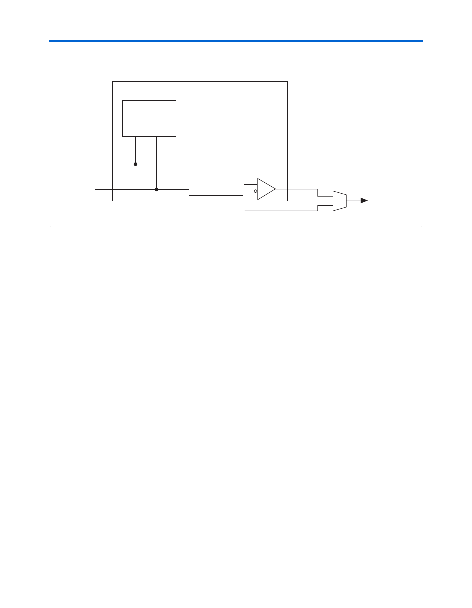
Figure 2–8. Receiver Input Buffer
Programmable Receiver Termination
The Stratix GX receiver buffer includes programmable on-chip
differential termination of 100, 120, or 150
Ω..
This assignment must be made per pin through the Assignment Editor in
the Quartus II software. Select Assignment Organizer > Options for
Individual Nodes Only > Stratix GX Termination Value
(Assignments
menu).
1
The proper termination settings should be selected and verified
accordingly before compilation.
The transmitter PLL input signal (inclk) drives the termination
resistance calibration circuit. The Quartus II software allows
receiver-only configurations in Stratix GX devices. However, if you use
the Quartus II software to remove the transmitter PLL in a receiver-only
configuration, you will see an incorrect value or unpredictable behavior
with the receiver input pin termination. If the rx_cruclk signal is
globally routed, the Quartus II software handles this automatically. If the
rx_cruclk
signal is not globally routed or routed using the inter-
quadrant line (IQ2), the Quartus II software returns a no-fit. In this
situation, you must add a transmitter PLL to your design.
If the pll_areset (analog reset) signal goes high, the RX_Vcm value is
less than the 1.1 V. This value varies unpredictably because the circuit is
tristated. RX_Vcm is referenced from the Stratix GX receiver analog power
supply.
Input Buffer
Input Pins
Internal Loopback
from Transmitter
Programmable
Equalizer
Programmable
Termination
To PLD