Yaskawa Z1000 AC Drive HVAC User Manual
Page 122
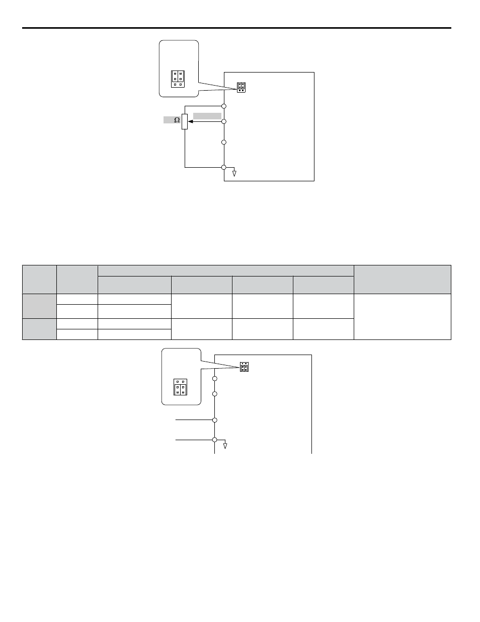
Drive
A1 Analog Input 1
0 to 10 V
AC Analog input common
2 k
+V 10.5 V, 20 mA power supply
A2 Analog Input 2
V
I
A1 A2
Jumper S1
Terminal A1/A2
Voltage/Current
Selection
V
I
A1 A2
Figure 4.12 Setting the Frequency Reference as a Voltage Signal at Terminal A1
Use the wiring example shown in
for any other analog input terminals. When using input terminals A1 and A2,
make sure Jumper S1 is set for voltage input.
Current Input
Input terminals A1 and A2 can accept a current input signal. Refer to
to set terminals A1 and A2 for current input.
Table 4.16 Analog Input Settings for Frequency Reference Using a Current Signal
Terminal
Signal
Level
Parameter Settings
Notes
Signal Level
Selection
Function
Selection
Gain
Bias
A1
4 to 20 mA
H3-01 = 2
H3-02 = 0
(Frequency
Reference Bias)
H3-03
H3-04
Make sure to set Jumper S1 on the
terminal board to “I” for current
input.
0 to 20 mA
H3-01 = 3
A2
4 to 20 mA
H3-09 = 2
H3-10 = 0
(Frequency Bias)
H3-11
H3-12
0 to 20 mA
H3-09 = 3
Drive
A1 Analog Input 1
0 or 4 to 20 mA
AC Analog input common
+V 10.5 V, 20 mA power supply
A2 Analog Input 2
V
I
A1 A2
Jumper S1
Terminal A1/A2
Voltage/Current
Selection
V
I
A1 A2
Figure 4.13 Setting the Frequency Reference as a Current Signal to Terminal A2
Switching between Main/Auxiliary Frequency References
The frequency reference input can be switched between the analog terminals A1 and A2 using multi-speed inputs.
Multi-Step Speed Selection on page 164
for details on using this function.
Setting 2: Serial Communication (APOGEE FLN, BACnet, MEMOBUS/Modbus, Metasys N2)
This setting requires entering the frequency reference via the RS-422/RS-485 serial communications port (control terminals
R+, R-, S+, and S-).
4.7 Basic Drive Setup Adjustments
122
YASKAWA ELECTRIC TOEP YAIZ1U 03A YASKAWA AC Drive – Z1000 User Manual