H3-01: terminal a1 signal level selection, H3-02: terminal a1 function selection, H3-09: terminal a2 signal level selection – Yaskawa Z1000 AC Drive HVAC User Manual
Page 169: H3-10: terminal a2 function selection
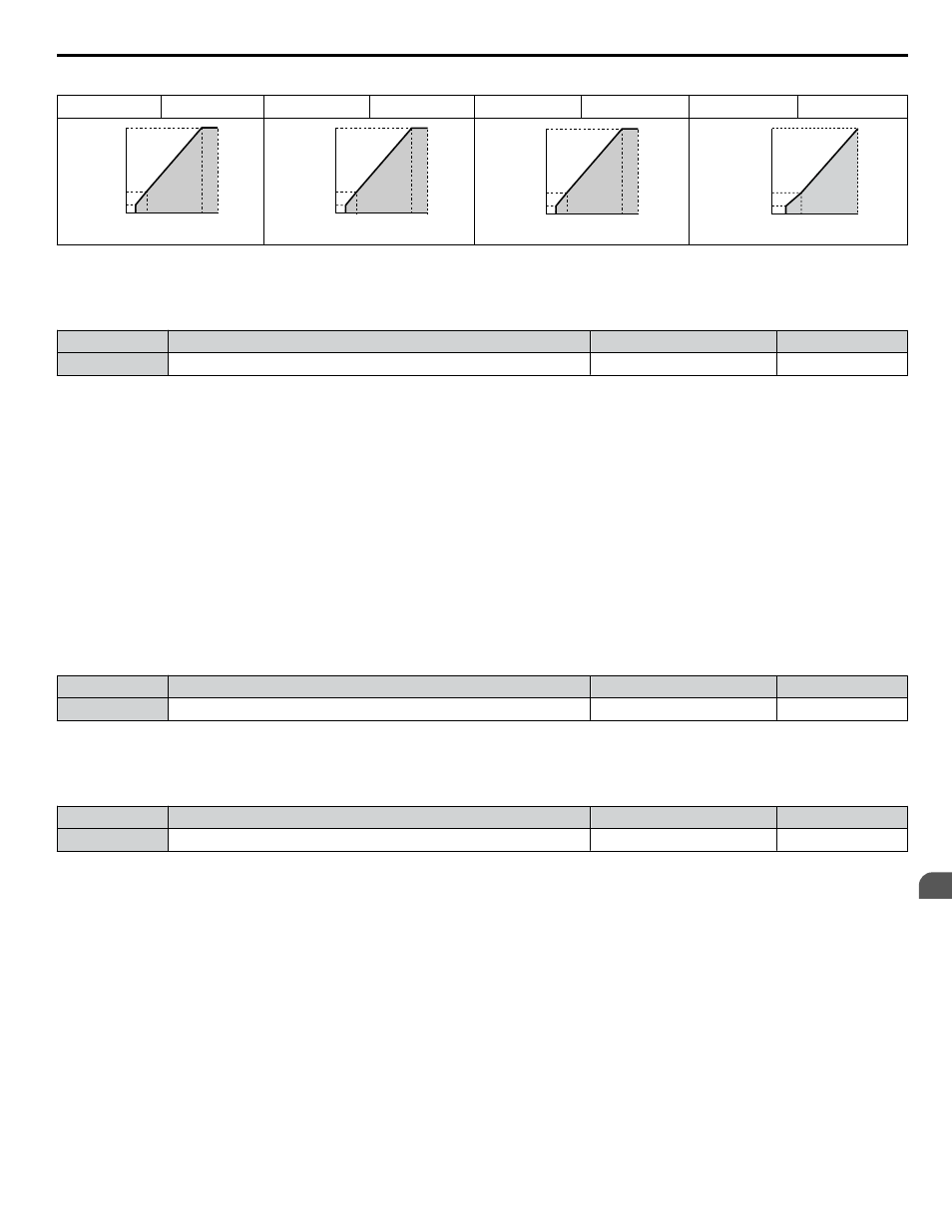
Table 4.37 Constant Output, Settings C to F
Setting = C
90 Hz
Setting = D
120 Hz
Setting = E
180 Hz
Setting = F
60 Hz
0
17.3
34.5
575
1.5 3
90
60
V
oltage (V)
Frequency (Hz)
0
17.3
34.5
575
1.5 3
120
60
V
oltage (V)
Frequency (Hz)
0
17.3
34.5
575
1.5 3
180
60
V
oltage (V)
Frequency (Hz)
0
17.3
575
1.5 3
60
34.5
V
oltage (V)
Frequency (Hz)
n
H3-01: Terminal A1 Signal Level Selection
Selects the input signal level for analog input A1. Set jumper S1 on the terminal board accordingly for voltage input or current
input.
No.
Name
Setting Range
Default
H3-01
Terminal A1 Signal Level Selection
0 to 3
0
Setting 0: 0 to 10 V with Zero Limit
The input level is 0 to 10 Vdc with zero limit. The minimum input level is limited to 0%, so that a negative input signal due
to gain and bias settings will be read as 0%.
Setting 1: 0 to 10 V without Zero Limit
The input level is 0 to 10 Vdc without zero limit. If the resulting voltage is negative after being adjusted by gain and bias
settings, then the motor will rotate in reverse.
Setting 2: 4 to 20 mA Current Input
The input level is 4 to 20 mA. Negative input values by negative bias or gain settings are limited to 0%.
Setting 3: 0 to 20 mA Current Input
The input level is 0 to 20 mA. Negative input values by negative bias or gain settings are limited to 0%.
n
H3-02: Terminal A1 Function Selection
Selects the input signal level for analog input A1.
No.
Name
Setting Range
Default
H3-02
Terminal A1 Function Selection
0 to 41
0
n
H3-09: Terminal A2 Signal Level Selection
Selects the input signal level for analog input A2. Set Jumper S1 on the terminal board accordingly for a voltage input or
current input.
No.
Name
Setting Range
Default
H3-09
Terminal A2 Signal Level Selection
0 to 3
2
Setting 0: 0 to 10 V with Zero Limit
The input level is 0 to 10 Vdc. Negative input values will be limited to 0.
Refer to Setting 0: 0 to 10 V with Zero Limit on
Setting 1: 0 to 10 V without Zero Limit
The input level is 0 to 10 Vdc. Negative input values will be accepted.
Refer to Setting 1: 0 to 10 V without Zero Limit on
Setting 2: 4 to 20 mA Current Input
The input level is 4 to 20 mA. Negative input values by negative bias or gain settings will be limited to 0%.
Setting 3: 0 to 20 mA Current Input
The input level is 0 to 20 mA. Negative input values by negative bias or gain settings will be limited to 0%.
n
H3-10: Terminal A2 Function Selection
Determines the function assigned to analog input terminal A2.
4.13 Advanced Drive Setup Adjustments
YASKAWA ELECTRIC TOEP YAIZ1U 03A YASKAWA AC Drive – Z1000 User Manual
169
4
Start-Up Programming & Operation