Alarm and error displays, Faults – Yaskawa Z1000 AC Drive HVAC User Manual
Page 195
u
Alarm and Error Displays
n
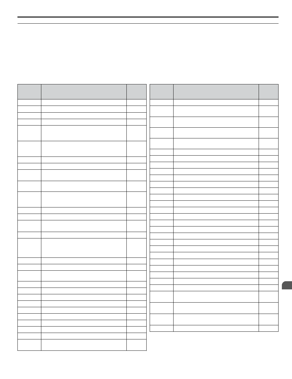
Faults
gives an overview of possible fault codes. Conditions such as overvoltages can trip faults and alarms. It is important
to distinguish between faults and alarms to determine the proper corrective actions.
When the drive detects a fault, the ALM indicator LED lights, the fault code appears on the HOA keypad, and the fault contact
Minor Faults and Alarms on page 196
for a list of alarm codes.
Table 5.5 Fault Displays
HOA
Keypad
Display
Name
Page
bAT
Digital Operator Battery Voltage Low
boL
Braking Transistor Overload Fault
bUS
Option Communication Error
CE
MEMOBUS/Modbus Communication Error
CPF11 to
CPF14
<1> <3>
Control Circuit Error
CPF16 to
CPF19
<1> <3>
Control Circuit Error
CPF02
A/D Conversion Error
CPF03
Control Board Connection Error
CPF06
<3>
EEPROM Memory Data Error
CPF07,
CPF08
Terminal Board Connection Error
CPF20,
CPF21
<2>
Control Circuit Error
CPF22
Hybrid IC Error
CPF23
Control Board Connection Error
CPF24
<3>
Drive Unit Signal Fault
CPF25
Terminal Board Not Connected
CPF26 to
CPF35,
CPF40 to
CPF43
Control Circuit Error
E5
SI-T3 Watchdog Timer Error
EF0
Option Card External Fault
EF1 to EF7 External Fault
(input terminal S1 to S7)
Err
EEPROM Write Error
FAn
Internal Fan Fault
FbH
Excessive PID Feedback
FbL
PID Feedback Loss
GF
Ground Fault
LF
Output Phase Loss
LF2
Current Imbalance
nSE
Node Setup Error
oC
Overcurrent
oFA00
<3>
Option Card Connection Error
(CN5-A)
HOA
Keypad
Display
Name
Page
oFA01
Option Card Fault (CN5-A)
oFA03 to
oFA06
Option Card Error
(CN5-A)
oFA10,
oFA11
Option Card Error
(CN5-A)
oFA12 to
oFA17
Option Card Connection Error
(CN5-A)
oFA30 to
oFA43
Comm Option Card Connection Error
(CN5-A)
oH
Heatsink Overheat
oH1
Heatsink Overheat
oH3
Motor Overheat Alarm (PTC input)
oH4
Motor Overheat Fault (PTC input)
oL1
Motor Overload
oL2
Drive Overload
oL3
Overtorque Detection 1
oL7
High Slip Braking oL
oPr
Operator Connection Fault
ov
Overvoltage
ov2
Overvoltage 2
PF
Input Phase Loss
rF
Braking Resistor Fault
rH
Dynamic Braking Resistor
rr
Dynamic Braking Transistor
SC
IGBT Short Circuit or Ground Fault
SEr
Too Many Speed Search Restarts
TdE
Time Data Error
TIE
Time Interval Error
TIM
Time Not Set
UL3
Undertorque Detection 1
UL6
Motor Underload
Uv1
<3>
Undervoltage
Uv2
<3>
Control Power Supply Undervoltage
Uv3
<3>
Soft Charge Circuit Fault
voF
Output Voltage Detection Fault
5.3 Drive Alarms, Faults, and Errors
YASKAWA ELECTRIC TOEP YAIZ1U 03A YASKAWA AC Drive – Z1000 User Manual
195
5
Troubleshooting