Switches and jumpers on the terminal board, 9 control circuit wiring – Yaskawa Z1000 AC Drive HVAC User Manual
Page 91
Advertising
u
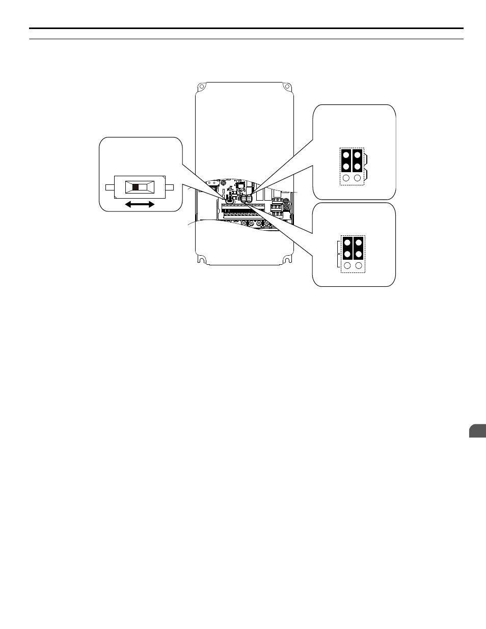
Switches and Jumpers on the Terminal Board
The terminal board is equipped with several switches used to adapt the drive I/Os to the external control signals.
shows the location of these switches.
Refer to Control I/O Connections on page 92
for setting instructions.
IG R+ R- S+ S- +V AC A1 A2 FM AM AC
FE S1 S2 S3 S4 S5 S6 S7
SN SC SP +P
M3 M4 M6
M1 M2 M5
MA MB MC
Jumper S5
Terminal AM/FM
Signal Selection
FM AM
V
I
DIP Switch S2
RS-422/485 Termination
Resistor
Off
On
Jumper S1
A1/A2 Voltage/Current
Selection
V
I
A1 A2
Figure 3.26 Locations of Jumpers and Switches on the Terminal Board
3.9 Control Circuit Wiring
YASKAWA ELECTRIC TOEP YAIZ1U 03A YASKAWA AC Drive – Z1000 User Manual
91
3
Electrical Installation
Advertising