Yaskawa Z1000 AC Drive HVAC User Manual
Page 348
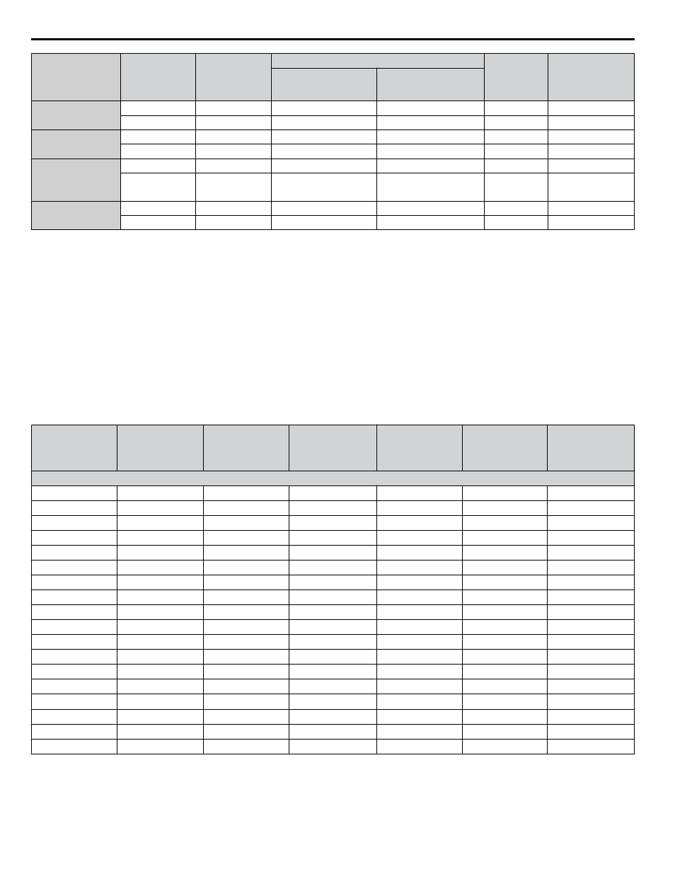
Wire Gauge
Terminal
Screws
Crimp Terminal
Model Number
Tool
Insulation
Cap
Model No.
Code
<1>
Machine No.
Die Jaw
4/0 AWG × 2P
4/0 AWG × 4P
M10
100-L10
YF-1, YET-150-1
TD-228, TD-214
TP-100
100-051-559
M12
100-L12
YF-1, YET-300-1
TD-324, TD-312
TP-100
100-051-560
250 / 300 kcmil
M10
R150-10
YF-1. YET-150-1
TD-229, TD-215
TP-150
100-051-272
M12
R150-12
YF-1, YET-300-1
TD-325, TD-313
TP-150
100-051-273
250 kcmil × 2P
250 kcmil × 4P
300 kcmil × 2P
300 kcmil × 4P
M10
150-L10
YF-1, YET-150-1
TD-229, TD-215
TP-150
100-051-561
M12
150-L12
YF-1, YET-300-1
TD-325, TD-313
TP-150
100-051-562
350 kcmil
400 kcmil
M10
200-10
YF-1, YET-300-1
TD-327, TD-314
TP-200
100-051-563
M12
R200-12
YF-1, YET-300-1
TD-327, TD-314
TP-200
100-051-275
<1> Codes refer to a set of three crimp terminals and three insulation caps. Prepare input and output wiring using two sets for each connection.
Example 1: Models with 300 kcmil for both input and output require one set for input terminals and one set for output terminals, so the user should
order two sets of [100-051-272].
Example 2: Models with 4/0 AWG × 2P for both input and output require two sets for input terminals and two sets for output terminals, so the user
should order four sets of [100-051-560].
Note:
Use crimp insulated terminals or insulated shrink tubing for wiring connections. Wires should have a continuous maximum allowable
temperature of 75 °C 600 Vac UL-approved vinyl-sheathed insulation.
Factory Recommended Branch Circuit Protection for UL Compliance
NOTICE: If a fuse is blown or a Ground Fault Circuit Interrupter (GFCI) is tripped, check the wiring and the selection of the peripheral devices.
Check the wiring and the selection of peripheral devices to identify the cause. Contact Yaskawa before restarting the drive or the peripheral
devices if the cause cannot be identified.
Yaskawa recommends installing one of the following types of branch circuit protection to maintain compliance with UL508C.
Semiconductor protective type fuses are preferred. Alternate branch circuit protection devices are also listed in
Table D.4 Factory Recommended Drive Branch Circuit Protection
Drive Model
Nominal
Output Power
HP
AC Drive Input
Amps
MCCB Rating
Amps
<1>
Time Delay Fuse
Rating Amps
<2>
Non-time Delay
Fuse Rating
Amps
<3>
Bussmann Semi-
conductor Fuse
Rating (Fuse
Ampere)
<4>
600 V Class
5A0003
2
3.6
15
6.25
10
FWP-50B (50)
5A0004
3
5.1
15
8
15
FWP-50B (50)
5A0006
5
8.3
15
12
20
FWP-60B (60)
5A0009
7.5
12
20
20
35
FWP-60B (60)
5A0011
10
16
30
25
45
FWP-70B (70)
5A0017
15
23
40
40
60
FWP-100B (100)
5A0022
20
31
60
50
90
FWP-100B (100)
5A0027
25
38
75
60
110
FWP-125A (125)
5A0032
30
45
75
75
125
FWP-125A (125)
5A0041
40
44
75
75
125
FWP-175A (175)
5A0052
50
54
100
90
150
FWP-175A (175)
5A0062
60
66
125
110
175
FWP-250A (250)
5A0077
75
80
150
125
225
FWP-250A (250)
5A0099
100
108
175
175
300
FWP-250A (250)
5A0125
125
129
225
225
350
FWP-350A (350)
5A0145
150
158
300
275
450
FWP-350A (350)
5A0192
200
228
400
350
600
FWP-600A (600)
5A0242
250
263
500
450
700
FWP-600A (600)
<1> Maximum MCCB Rating is 15 A, or 200 % of drive input current rating, whichever is larger. MCCB voltage rating must be 600 VAC or greater.
<2> Maximum Time Delay fuse is 175% of drive input current rating. This covers any Class CC, J or T class fuse.
<3> Maximum Non-time Delay fuse is 300% of drive input current rating. This covers any CC, J or T class fuse.
<4> When using semiconductor fuses, Bussman FWP are required for UL compliance.
<5> Class L fuse is also approved for this rating.
D.3 UL and CSA Standards
348
YASKAWA ELECTRIC TOEP YAIZ1U 03A YASKAWA AC Drive – Z1000 User Manual