Yaskawa Z1000 AC Drive HVAC User Manual
Page 208
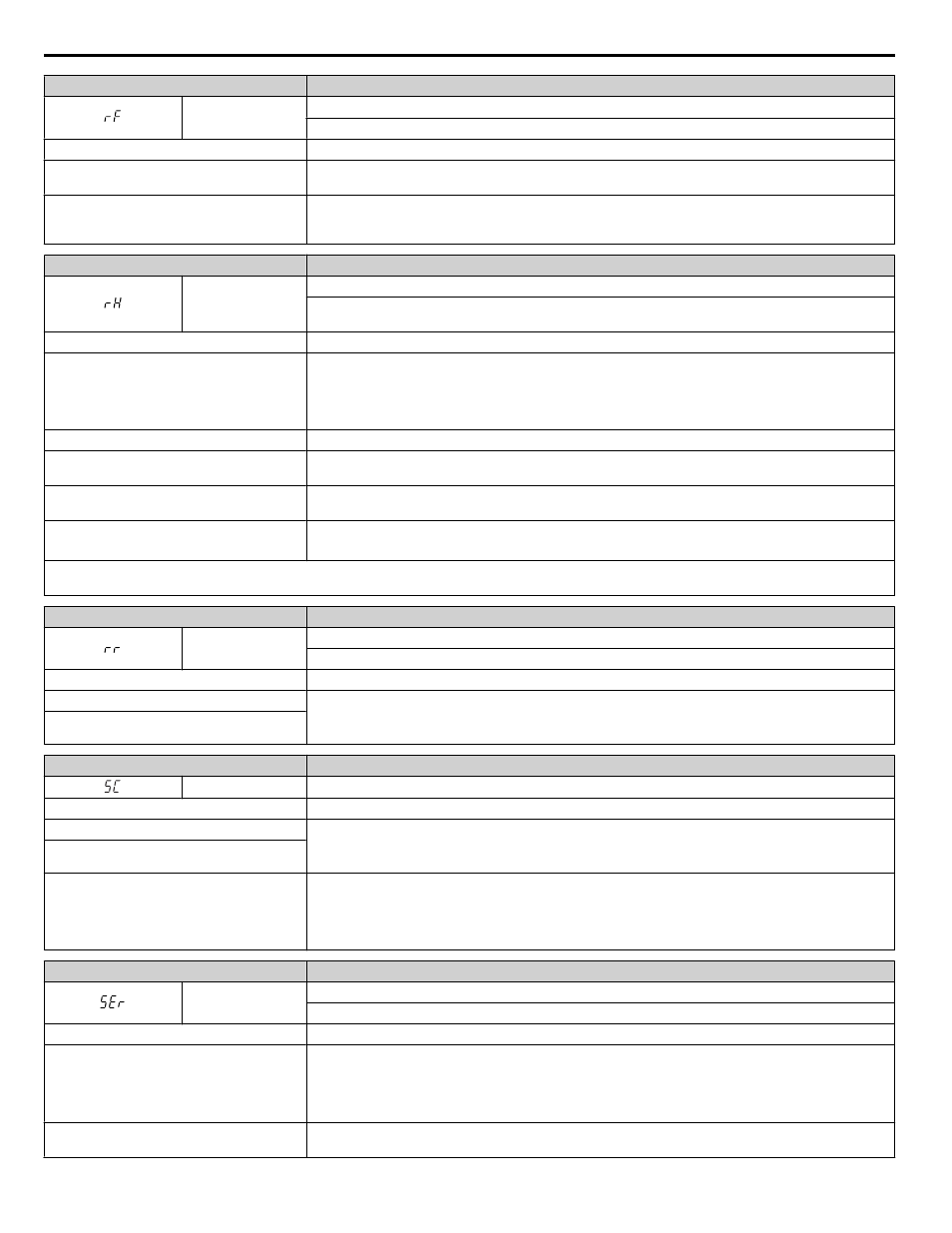
Digital Operator Display
Fault Name
rF
Braking Resistor Fault
The resistance of the braking resistor is too low.
Cause
Possible Solution
The proper braking resistor option has not
been installed
Select a braking resistor option that it fits the drive braking transistor specification.
A regenerative converter, regenerative unit, or
braking unit is being used and the
⊕1 or ⊕3
terminal is connected to
⊖ terminal
Set L8-55 to 0 to disable the braking transistor protection selection.
Digital Operator Display
Fault Name
rH
Braking Resistor Overheat
Braking resistor protection was triggered.
Fault detection is enabled when L8-01 = 1 (disabled as a default).
Cause
Possible Solution
Deceleration time is too short and excessive
regenerative energy is flowing back into the
drive
• Check the load, deceleration time, and speed.
• Reduce the load inertia.
• Increase the deceleration times (C1-01 to C1-04).
• Replace the dynamic braking option with a larger device that can handle the power that is discharged.
The duty cycle is too high
Check the duty cycle. Maximum of 3% duty cycle is available when L8-01 = 1.
Excessive braking inertia
Recalculate braking load and braking power. Reduce the braking load by adjusting braking resistor
settings.
The braking operation duty cycle is too high Check the braking operation duty cycle. Braking resistor protection for ERF-type braking resistors
(L8-01 = 1) allows a braking duty cycle of maximum 3%.
The proper braking resistor has not been
installed
• Check the specifications and conditions for the braking resistor device.
• Select the optimal braking resistor.
Note:
The magnitude of the braking load trips the braking resistor overheat alarm, NOT the surface temperature. Using the braking resistor more
frequently than its rating permits will trip the alarm even when the braking resistor surface is not very hot.
Digital Operator Display
Fault Name
rr
Dynamic Braking Transistor
The built-in dynamic braking transistor failed.
Cause
Possible Solution
The braking transistor is damaged
• Cycle power to the drive and check for reoccurrence of the fault.
• Replace either the control board or the entire drive. For instructions on replacing the control board,
contact Yaskawa or a Yaskawa representative.
The control circuit is damaged
Digital Operator Display
Fault Name
SC
IGBT Short Circuit or Ground Fault
Cause
Possible Solution
IGBT fault
• Check motor wiring.
• Turn off the power supply, then turn it on. If the problem continues, contact your Yaskawa
representative or the nearest Yaskawa sales office.
IGBT short circuit detection circuit fault
The drive is damaged
• Check the drive output side short circuit for a broken output transistor
B1 and U/T1, V/T2, W/T3
– and U/T1, V/T2, W/T3
• Contact your Yaskawa representative or nearest Yaskawa sales office.
Digital Operator Display
Fault Name
SEr
Too Many Speed Search Restarts
The number of Speed Search restarts exceeded the value set to b3-19.
Cause
Possible Solution
Parameters related to Speed Search are set to
the wrong values
• Reduce the detection compensation gain during Speed Search (b3-10).
• Increase the current level when attempting Speed Search (b3-17).
• Increase the detection time during Speed Search (b3-18).
• Repeat Auto-Tuning.
The motor is coasting in the opposite direction
of the Run command
Set b3-14 to 1 to enable Bi-Directional Speed Search.
5.4 Fault Detection
208
YASKAWA ELECTRIC TOEP YAIZ1U 03A YASKAWA AC Drive – Z1000 User Manual