E1-01: input voltage setting – Yaskawa Z1000 AC Drive HVAC User Manual
Page 128
n
E1-01: Input Voltage Setting
Adjusts the levels of some protective features of the drive (overvoltage, Stall Prevention, etc.). Set this parameter to the nominal
voltage of the AC power supply.
NOTICE: Set parameter E1-01 to match the input voltage of the drive. Drive input voltage (not motor voltage) must be set in E1-01 for the
protective features to function properly. Failure to set the correct drive input voltage will result in improper drive operation.
No.
Parameter Name
Setting Range
Default
E1-01
Input Voltage Setting
445.6 to 733.1 V
661.3 V
E1-01 Related Values
The input voltage setting determines the overvoltage and undervoltage detection levels, the KEB function, and the overvoltage
suppression function.
Voltage
Setting Value of E1-01
(Approximate Values)
Uv Detection Level (L2-05)
600 V Class
All settings
475 V
n
V/f Pattern Settings E1-04 to E1-13
If E1-03 is set to a preset V/f pattern (i.e., a value other than F), the user can monitor the V/f pattern in parameters E1-04
through E1-13. To create a new V/f pattern, set E1-03 to F.
Refer to V/f Pattern on page 128
pattern.
Note:
Certain E1- parameters might not be visible depending on the control mode.
Refer to Parameter List on page 261
No.
Parameter Name
Setting Range
Default
E1-04
Maximum Output Frequency
40.0 to 240.0 Hz
<1>
E1-05
Maximum Voltage
0.0 to 733.1 V
<1>
E1-06
Base Frequency
0.0 to 240.0 Hz
<1>
E1-07
Middle Output Frequency
0.0 to 240.0 Hz
30.0 Hz
E1-08
Middle Output Frequency Voltage
0.0 to 733.1 V
143.8 V
E1-09
Minimum Output Frequency
0.0 to 240.0 Hz
<1>
E1-10
Minimum Output Frequency Voltage
0.0 to 733.1 V
<2>
E1-11
Middle Output Frequency 2
0.0 to 240.0 Hz
0.0 Hz
<3>
E1-12
Middle Output Frequency Voltage 2
0.0 to 733.1 V
0.0 V
<3>
E1-13
Base Voltage
0.0 to 733.1 V
0.0 V
<1> Default setting is dependent on parameter A1-02, Control Mode Selection.
<2> Default setting is dependent on parameter o2-04, Drive Model Selection.
<3> Parameter ignored when E1-11 and E1-12 are set to 0.0.
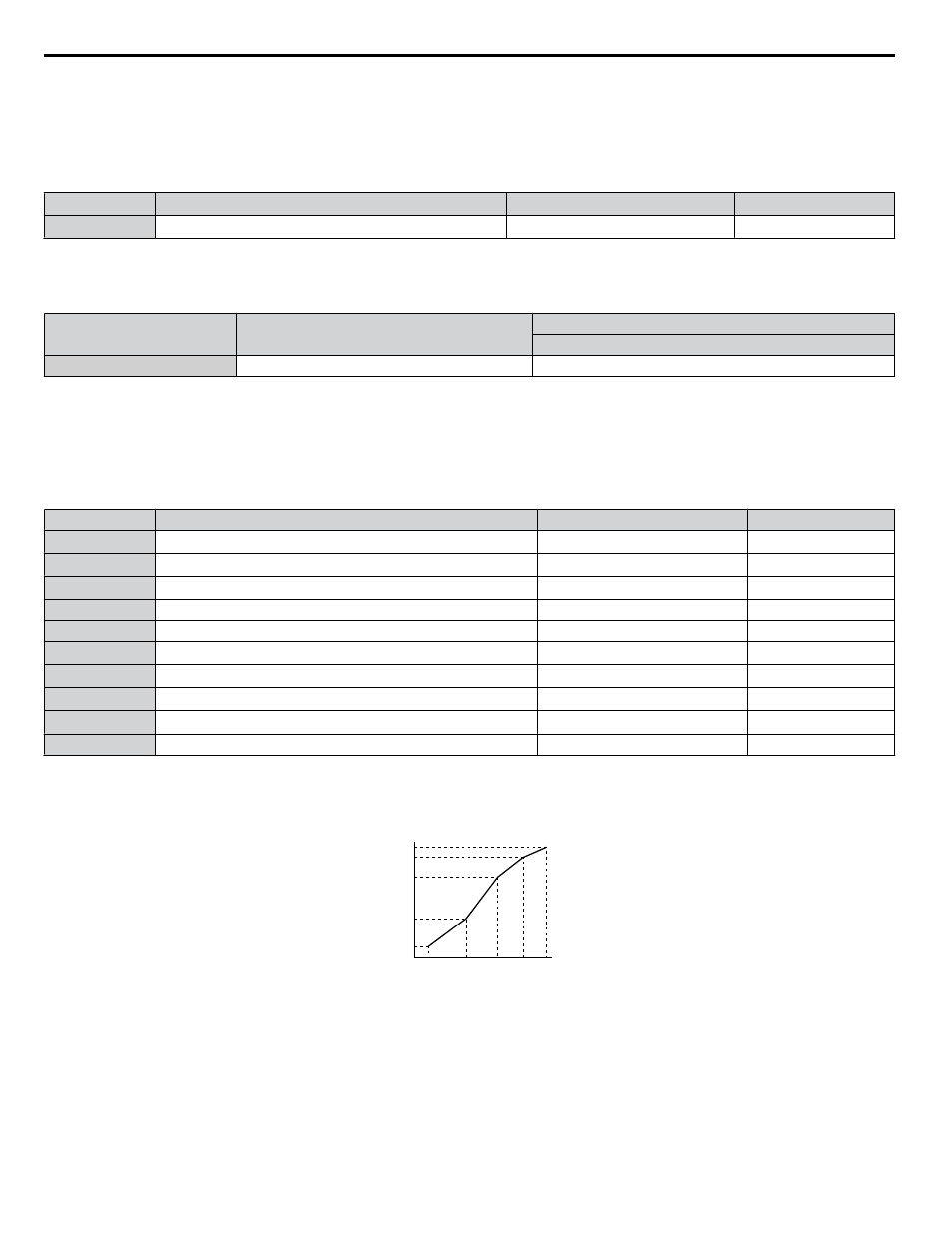
Output Voltage (V)
Frequency (Hz)
E1-05
E1-12
E1-13
E1-08
E1-10
E1-09
E1-07 E1-06 E1-11 E1-04
Figure 4.22 V/f Pattern
Note:
1. The following condition must be true when setting up the V/f pattern: E1-09 ≤ E1-07 < E1-06 ≤ E1-11 ≤ E1-04
2. To make the V/f pattern a straight line below E1-06, set E1-09 equal to E1-07. In this case the E1-08 setting is disregarded.
3. E1-03 is unaffected when the drive is initialized, but E1-04 through E1-13 return to their default values.
4. Only use E1-11, E1-12, and E1-13 to fine-tune the V/f pattern in the constant output range. These parameters rarely need to be changed.
4.7 Basic Drive Setup Adjustments
128
YASKAWA ELECTRIC TOEP YAIZ1U 03A YASKAWA AC Drive – Z1000 User Manual