Main circuit connection diagram, 8 main circuit wiring – Yaskawa Z1000 AC Drive HVAC User Manual
Page 85
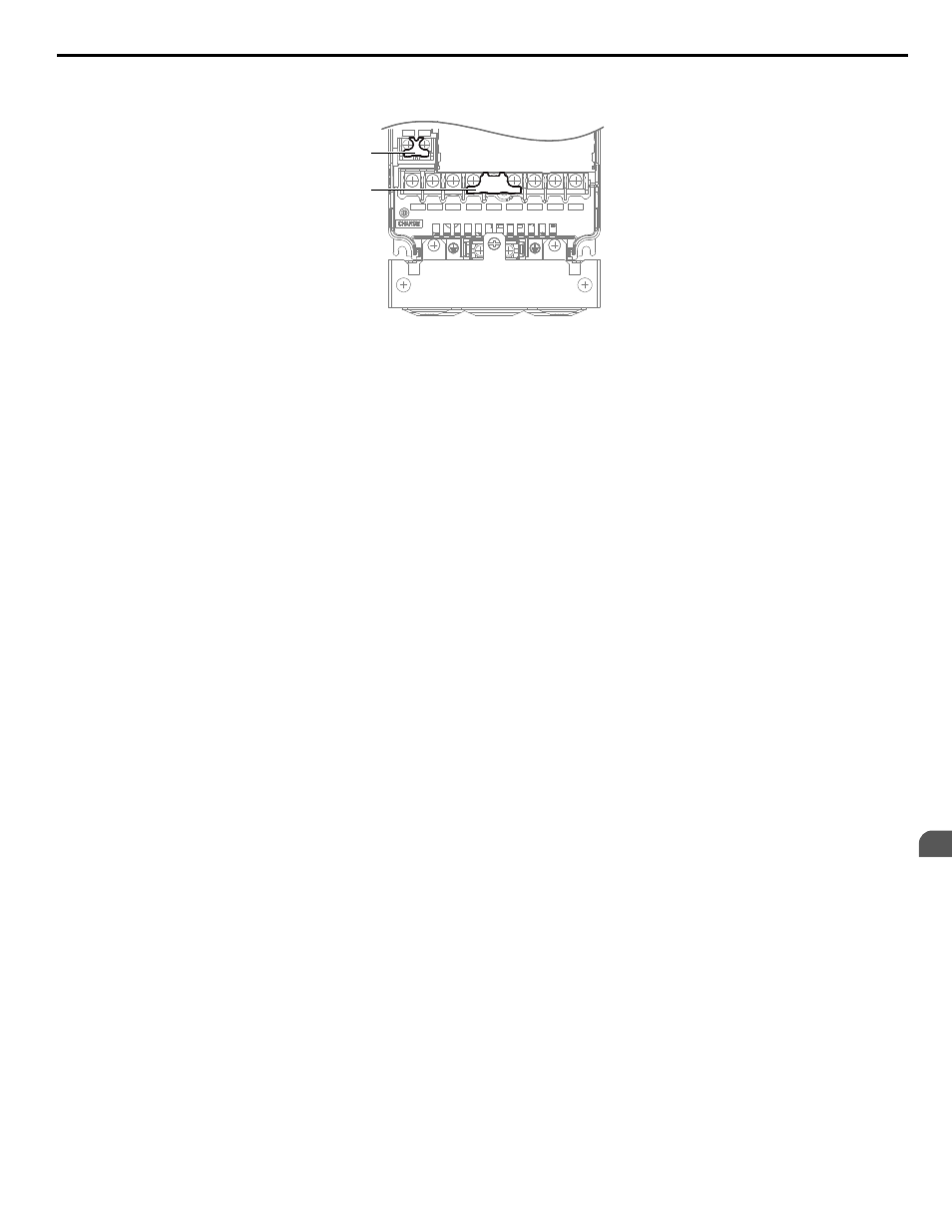
Models 5A0003 to 5A0032 have a cover placed over the DC bus and braking circuit terminals prior to shipment to help prevent
miswiring. Use wire cutters to cut away covers as needed for terminals.
R/L1 S/L2 T/L3
_
+1
+2
U/T1
V/T2
W/T3
B1
B2
A
B
A – Braking circuit protective cover
B – DC bus protective cover
Figure 3.19 Protecting Cover to Prevent Miswiring (Model 5A0011)
n
Main Circuit Connection Diagram
Refer to Main Circuit Connection Diagram on page 73
when wiring terminals on the main power circuit of the drive.
WARNING! Fire Hazard. The braking resistor connection terminals are B1 and B2. Do not connect braking resistors to any other terminals.
Improper wiring connections could cause the braking resistor to overheat and cause death or serious injury by fire. Failure to comply may
result in damage to the braking circuit or drive.
3.8 Main Circuit Wiring
YASKAWA ELECTRIC TOEP YAIZ1U 03A YASKAWA AC Drive – Z1000 User Manual
85
3
Electrical Installation