Yaskawa Z1000 AC Drive HVAC User Manual
Page 130
n
E5-07: Motor q-Axis Inductance (Lq)
Sets the q-Axis inductance in 0.01 mH units.
No.
Parameter Name
Setting Range
Default
E5-07
Motor q-Axis Inductance
0.00 to 600.00 mH
Determined by
o2-04
n
E5-09: Motor Induction Voltage Constant 1 (Ke)
Sets the induced peak voltage per phase in units of 0.1 mV/(rad/s) [electrical angle]. Set this parameter when using an IPM
motor with variable torque.
No.
Parameter Name
Setting Range
Default
E5-09
Motor Induction Voltage Constant 1
0.0 to 2000.0 mV/(rad/s)
Determined by
o2-04
Note:
Set E5-24 to 0 when setting E5-09. However, setting both E5-09 and E5-24 to 0 will trigger an alarm. An alarm will also be triggered if
neither E5-09 nor E5-24 are set to 0.
n
E5-24: Motor Induction Voltage Constant 2 (Ke)
Set the induced phase-to-phase rms voltage in units of 0.1 mV/(r/min) [mechanical angle]. Set this parameter when using an
SPM Motor.
No.
Parameter Name
Setting Range
Default
E5-24
Motor Induction Voltage Constant 2
0.0 to 6500.0 mV/(r/min)
Determined by
o2-04
Note:
Set E5-24 to 0.0 when setting E5-09. However, setting both E5-09 and E5-24 to 0.0 will trigger an alarm. An alarm will also be triggered
if neither E5-09 nor E5-24 are set to 0.0.
n
H3-03, H3-04: Terminal A1 Gain and Bias Settings
Parameter H3-03 sets the level of the selected input value that is equal to 10 Vdc (20 mA) input at terminal A1 (gain).
Parameter H3-04 sets the level of the selected input value that is equal to 0 V (4 mA, 0 mA) input at terminal A1 (bias).
Use both parameters to adjust the characteristics of the analog input signal to terminal A1.
No.
Name
Setting Range
Default
H3-03
Terminal A1 Gain Setting
-999.9 to 999.9%
100.0%
H3-04
Terminal A1 Bias Setting
-999.9 to 999.9%
0.0%
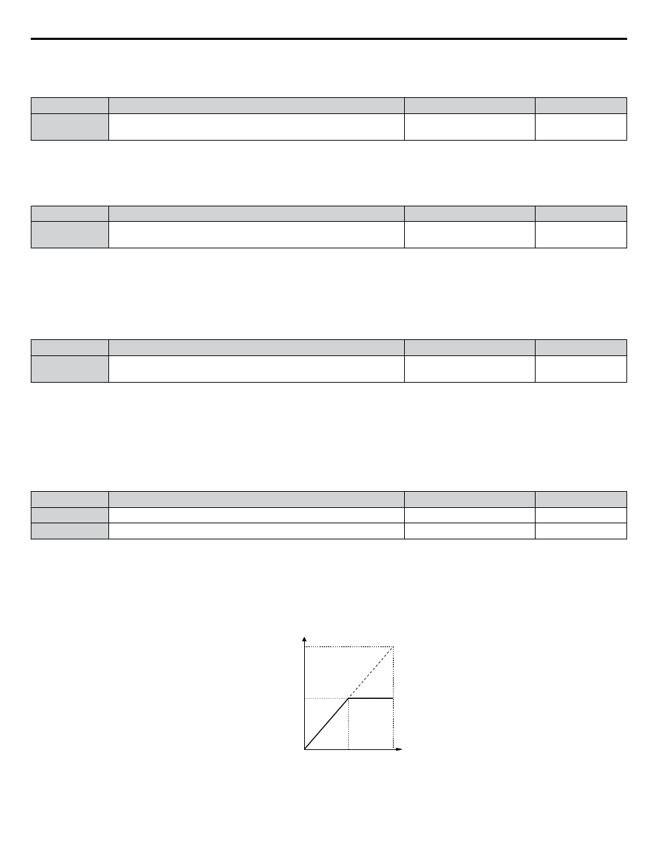
Setting Examples
• Gain H3-03 = 200%, bias H3-04 = 0, terminal A1 as frequency reference input (H3-02 = 0):
A 10 Vdc input is equivalent to a 200% frequency reference and 5 Vdc is equivalent to a 100% frequency reference. Since
the drive output is limited by the maximum frequency parameter (E1-04), the frequency reference will be equal to E1-04
above 5 Vdc.
H3-01 = 0
10 V
5 V
0 V
Gain = 200 %
100 %
Frequency
reference
Bias = 0 %
E1-04
Figure 4.23 Frequency Reference Setting by Analog Input with Increased Gain
• Gain H3-03 = 100%, bias H3-04 = -25%, terminal A1 as frequency reference input:
4.7 Basic Drive Setup Adjustments
130
YASKAWA ELECTRIC TOEP YAIZ1U 03A YASKAWA AC Drive – Z1000 User Manual