Yaskawa Z1000 AC Drive HVAC User Manual
Page 131
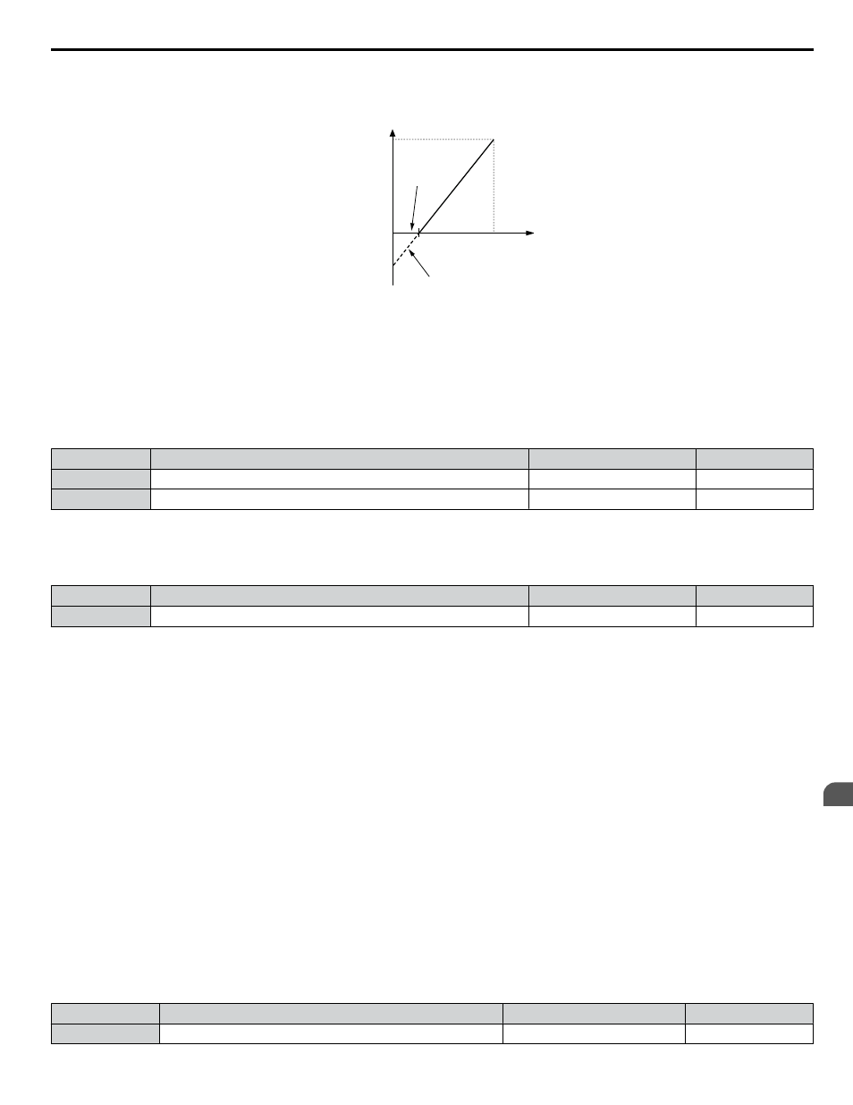
An input of 0 Vdc will be equivalent to a -25% frequency reference.
When parameter H3-01 = 0, the frequency reference is 0% between 0 and 2 Vdc input.
0
2.0 V
10 V
100 %
Frequency
reference
-25%
H3-01 = 0
H3-01 = 1
H3-01 = 0
Analog Input
Voltage
Figure 4.24 Frequency Reference Setting by Analog Input with Negative Bias
n
H3-11, H3-12: Terminal A2 Gain and Bias Setting
Parameter H3-11 sets the level of the input value selected that is equal to 10 Vdc input or 20 mA input to terminal A2.
Parameter H3-12 sets the level of the input value selected that is equal to 0 V, 4 mA or 0 mA input at terminal A2.
Use both parameters to adjust the characteristics of the analog input signal to terminal A2. The setting works in the same way
as parameters H3-03 and H3-04 for analog input A1.
No.
Name
Setting Range
Default
H3-11
Terminal A2 Gain Setting
-999.9 to 999.9%
100.0%
H3-12
Terminal A2 Bias Setting
-999.9 to 999.9%
0.0%
n
L2-01: Momentary Power Loss Operation Selection
When a momentary power loss occurs (DC bus voltage falls below the level set in L2-05), the drive can automatically return
to the operation it was performing prior to the power loss based on certain conditions.
No.
Name
Setting Range
Default
L2-01
Momentary Power Loss Operation Selection
0 to 2
2
Setting 0: Disabled
If power is not restored within 15 ms, a Uv1 fault will result and the motor coasts to stop.
Setting 1: Recover within L2-02
When a momentary power loss occurs, the drive output will be shut off. If the power returns within the time set to parameter
L2-02, the drive will perform Speed Search and attempt to resume operation. If the power does not return within this time, it
will trigger a Uv1 fault.
Setting 2: Recover as long as CPU Has Power
When a momentary power loss occurs, the drive output will be shut off. If the power returns and the drive control circuit has
power, the drive will attempt to perform Speed Search and resume the operation. This will not trigger a Uv1 fault.
Notes on Settings 1 and 2
• “Uv” will flash on the operator while the drive is attempting to recover from a momentary power loss. A fault signal is not
output at this time.
• When using a magnetic contactor between the motor and the drive, keep the magnetic contactor closed as long as the drive
attempts to restart with Speed Search.
n
L2-02: Momentary Power Loss Ride-Thru Time
Sets the maximum time allowed to ride through a power loss. If power loss operation exceeds this time, the drive will attempt
to accelerate back to the frequency reference. This parameter is valid if L2-01 = 1.
Note:
The amount of time the drive is capable of recovering after a power loss is determined by the capacity of the drive. Drive capacity determines
the upper limit for L2-02.
No.
Name
Setting Range
Default
L2-02
Momentary Power Loss Ride-Thru Time
0.0 to 25.5 s
Determined by o2-04
4.7 Basic Drive Setup Adjustments
YASKAWA ELECTRIC TOEP YAIZ1U 03A YASKAWA AC Drive – Z1000 User Manual
131
4
Start-Up Programming & Operation