H3: multi-function analog inputs – Yaskawa Z1000 AC Drive HVAC User Manual
Page 287
u
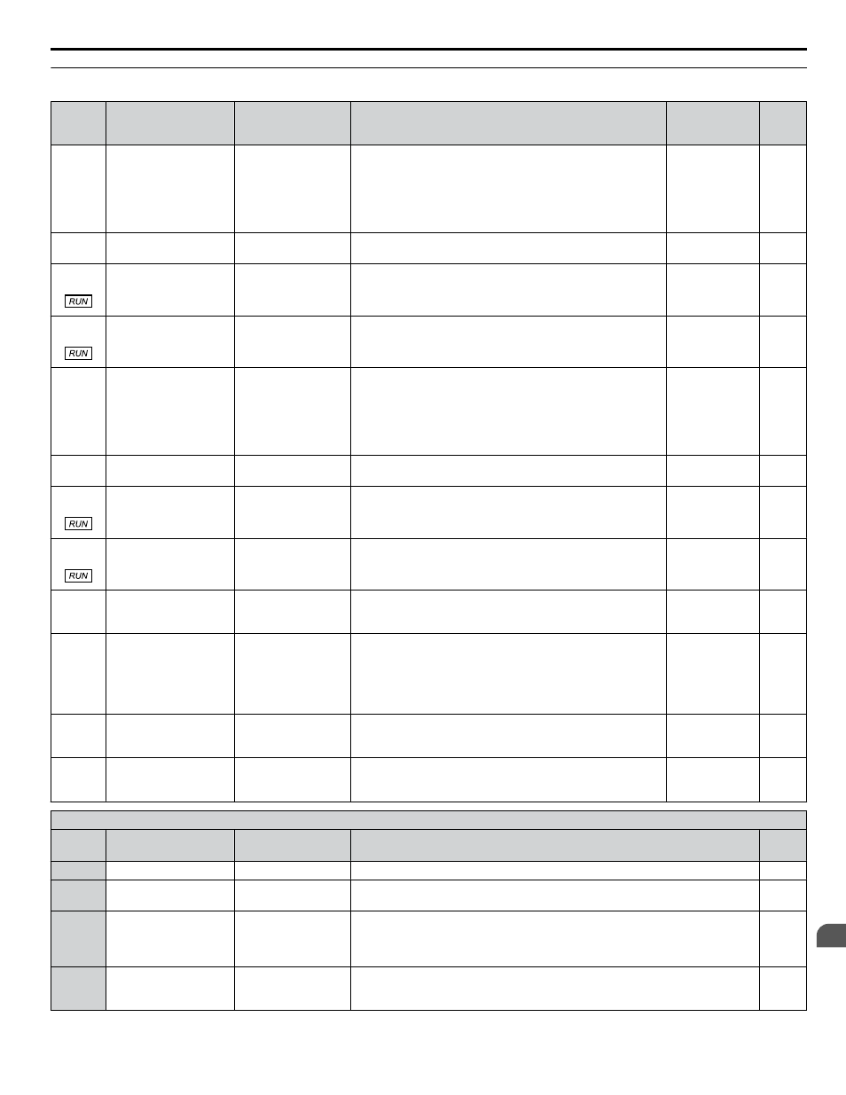
H3: Multi-Function Analog Inputs
No.
(Addr.
Hex)
Name
LCD Display
Description
Values
Page
H3-01
(410)
Terminal A1 Signal
Level Selection
Term A1 Level
0: 0-10V,
(LowLim=0)
1: 0-10V, (BipolRef)
2: 4-20 mA
3: 0-20 mA
0: 0 to 10 V with zero limit
1: 0 to 10 V without zero limit
2: 4-20 mA
3: 0-20 mA
Note:
Use jumper switch S1 to set input terminal A1
for current or voltage.
Default: 0
Range: 0 to 3
H3-02
(434)
Terminal A1 Function
Selection
Term A1 FuncSel
Sets the function of terminal A1.
Default: 0
Range: 0 to 26
H3-03
(411)
Terminal A1 Gain
Setting
Terminal A1 Gain
Sets the level of the input value selected in H3-02 when 10 V
is input at terminal A1.
Default: 100.0%
Min.: -999.9
Max.: 999.9
H3-04
(412)
Terminal A1 Bias
Setting
Terminal A1 Bias
Sets the level of the input value selected in H3-02 when 0 V is
input at terminal A1.
Default: 0.0%
Min.: -999.9
Max.: 999.9
H3-09
(417)
Terminal A2 Signal
Level Selection
Term A2 Level
0: 0-10V,
(LowLim=0)
1: 0-10V, (BipolRef)
2: 4-20 mA
3: 0-20 mA
0: 0 to 10 V with zero limit
1: 0 to 10 V without zero limit
2: 4 to 20 mA
3: 0 to 20 mA
Note:
Use jumper switch S1 to set input terminal A2
for current or voltage input signal.
Default: 2
Range: 0 to 3
H3-10
(418)
Terminal A2 Function
Selection
Term A2 FuncSel
Sets the function of terminal A2.
Default: 0
Range: 0 to 26
H3-11
(419)
Terminal A2 Gain
Setting
Terminal A2 Gain
Sets the level of the input value selected in H3-10 when 10 V
(20 mA) is input at terminal A2.
Default: 100.0%
Min.: -999.9
Max.: 999.9
H3-12
(41A)
Terminal A2 Bias
Setting
Terminal A2 Bias
Sets the level of the input value selected in H3-10 when 0 V (0
or 4 mA) is input at terminal A2.
Default: 0.0%
Min.: -999.9
Max.: 999.9
H3-13
(41B)
Analog Input Filter Time
Constant
A1/A2 Filter T
Sets a primary delay filter time constant for terminals A1 and
A2. Used for noise filtering.
Default: 0.03 s
Min.: 0.00
Max.: 2.00
–
H3-14
(41C)
Analog Input Terminal
Enable Selection
A1/A2 Sel
1: A1 Available
2: A2 Available
3: A1/A2 Available
Determines which analog input terminals will be enabled when
a digital input programmed for “Analog input enable”
(H1- = C) is activated.
1: Terminal A1 only
2: Terminal A2 only
3: Terminals A1 and A2
Default: 2
Range: 1 to 3
–
H3-16
(2F0)
Terminal A1 Offset
Term A1 Offset
Adds an offset when the analog signal to terminal A1 is at 0 V. Default: 0
Min.: -500
Max.: 500
–
H3-17
(2F1)
Terminal A2 Offset
Term A2 Offset
Adds an offset when the analog signal to terminal A2 is at 0 V. Default: 0
Min.: -500
Max.: 500
–
H3 Multi-Function Analog Input Settings
H3-
Setting
Function
LCD Display
Description
Page
0
Frequency bias
Freq Ref Bias
10 V = E1-04 (maximum output frequency)
1
Frequency gain
Freq Ref Gain
0 to 10 V signal allows a setting of 0 to 100%. -10 to 0 V signal allows a setting
of -100 to 0%.
2
Auxiliary frequency
reference 1
(used as a Multi-Step
Speed 2)
Aux Reference1
10 V = E1-04 (maximum output frequency)
3
Auxiliary frequency
reference 2
(3rd step analog)
Aux Reference2
10 V = E1-04 (maximum output frequency)
B.7 H Parameters: Multi-Function Terminals
YASKAWA ELECTRIC TOEP YAIZ1U 03A YASKAWA AC Drive – Z1000 User Manual
287
B
Parameter List