Installing input fuses – Yaskawa Z1000 AC Drive HVAC User Manual
Page 247
Reducing Radiated and Radio Frequency Noise
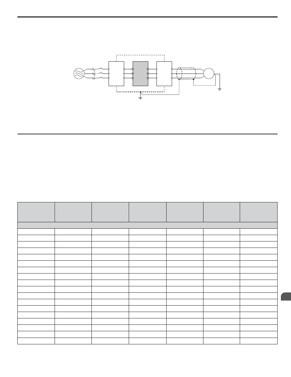
The drive, input lines, and output lines generate radio frequency noise. Use noise filters on input and output sides and install
the drive in a metal enclosure panel to reduce radio frequency noise.
Note:
The cable running between the drive and motor should be as short as possible.
C
E
D
B
F
A
R/L1
MCCB
S/L2
T/L3
U/T1
V/T2
W/T3
M
G
A – Metal enclosure
B – Power supply
C – Noise filter
D – Drive
E – Noise filter
F – Shielded motor cable
G – Motor
Figure 6.13 Reducing Radio Frequency Noise
u
Installing Input Fuses
NOTICE: If a fuse is blown or a Ground Fault Circuit Interrupter (GFCI) is tripped, check the wiring and the selection of the peripheral devices.
Check the wiring and the selection of peripheral devices to identify the cause. Contact Yaskawa before restarting the drive or the peripheral
devices if the cause cannot be identified.
Factory Recommended Branch Circuit Protection for UL Compliance
NOTICE: If a fuse is blown or a Ground Fault Circuit Interrupter (GFCI) is tripped, check the wiring and the selection of the peripheral devices.
Check the wiring and the selection of peripheral devices to identify the cause. Contact Yaskawa before restarting the drive or the peripheral
devices if the cause cannot be identified.
Yaskawa recommends installing one of the following types of branch circuit protection to maintain compliance with UL508C.
Table 6.3 Factory Recommended Drive Branch Circuit Protection
Drive Model
Nominal
Output Power
HP
AC Drive Input
Amps
MCCB Rating
Amps
<1>
Time Delay Fuse
Rating Amps
<2>
Non-time Delay
Fuse Rating
Amps
<3>
Bussmann Semi-
conductor Fuse
Rating (Fuse
Ampere)
<4>
600 V Class
5A0003
2
3.6
15
6.25
10
FWP-50B (50)
5A0004
3
5.1
15
8
15
FWP-50B (50)
5A0006
5
8.3
15
12
20
FWP-60B (60)
5A0009
7.5
12
20
20
35
FWP-60B (60)
5A0011
10
16
30
25
45
FWP-70B (70)
5A0017
15
23
40
40
60
FWP-100B (100)
5A0022
20
31
60
50
90
FWP-100B (100)
5A0027
25
38
75
60
110
FWP-125A (125)
5A0032
30
45
75
75
125
FWP-125A (125)
5A0041
40
44
75
75
125
FWP-175A (175)
5A0052
50
54
100
90
150
FWP-175A (175)
5A0062
60
66
125
110
175
FWP-250A (250)
5A0077
75
80
150
125
225
FWP-250A (250)
5A0099
100
108
175
175
300
FWP-250A (250)
5A0125
125
129
225
225
350
FWP-350A (350)
5A0145
150
158
300
275
450
FWP-350A (350)
5A0192
200
228
400
350
600
FWP-600A (600)
5A0242
250
263
500
450
700
FWP-600A (600)
<1> Maximum MCCB Rating is 15 A, or 200 % of drive input current rating, whichever is larger. MCCB voltage rating must be 600 VAC or greater.
6.5 Installing Peripheral Devices
YASKAWA ELECTRIC TOEP YAIZ1U 03A YASKAWA AC Drive – Z1000 User Manual
247
6
Peripheral Devices & Options